RSLogix 5 IO File Help

lillquist

Member
Join Date
Dec 2017
Location
Denver
Posts
7
If you take a look at the picture attached you can see that both I:000/0-4 and O:000/0-4 are used.

I was under the impression that the "000" in 0:000/0 was at least a logical slot number and therefore that any bit in the input and output files can only be used by either input or output.

The other issue is that with O:000/0-4 the total number of output bits goes to 36 and there are only 32 outputs points on the physical system as seen in the other attachment.

Any help is appreciated!

Lid Return Logix 5 IO tables.jpg Lid Return Physical IOs.jpg
 
I was under the impression that the "000" in 0:000/0 was at least a logical slot number and therefore that any bit in the input and output files can only be used by either input or output.

Not a "slot" number, but a "group" number. A group may occupy more than one physical slot within a chassis.
 
Like OkiePC said, the I/O image table in the PLC-5 existed for ALL potential I/O, whether it was there or not.

In the old days of PLC-2, it was common practice to write to unused "Output" addresses for internal coils (what might be a "B3" address in PLC-5 parlance). Because there was no output card, it didn't affect anything. Memory was expensive back in those days.


I've seen a few cases in really old PLC-5 applications where that practice continued. It's possible in your case. I had first suspected you had a case of "Complimentary I/O" (what Okie was referring to "in certain cases"), but looking at the physical rack, that's not the case here.

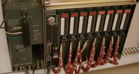
Instead, you appear to have "Double-slot addressing", where the first TWO 8-bit input cards (red labels) are in the first "slot" register (I:000/0 - 7; I:000/10 - 17 respectively), and the other two 8-bit input cards are in I:001. These are then followed by the first 2 8-bit output modules (orange labels) in O:002, and the last 2 cards are in O:003.

This accounts for everything in your Usage Map.

HTH
 
I've seen a few cases in really old PLC-5 applications where that practice continued. It's possible in your case.
HTH

This is what I'm thinking, mostly because these 5 bits take me over the physical output limit. It seems like these 5 extra bits have to be used as internal memory.
Another reason is that this overlap of input and outputs is a common theme among other programs at this site so maybe the original programmer was used to doing things a certain way.

Thanks for all the help!!
 
suggestion:

take a look at the "Switches" tab of the processor's status feature and tell us what it says for the "Addressing Mode" setting ... that will help the forum nail down what configuration you're dealing with ...

IMPORTANT:

use the "Switches" tab - and do NOT give us the "Rack Addressing" entry from the "IO Configuration" feature ... that's just "documentation" and it might not be set correctly ...
 
Another reason is that this overlap of input and outputs is a common theme among other programs at this site so maybe the original programmer was used to doing things a certain way.

Maybe. "Complimentary I/O" was also a popular technique back in the day, where Input & Output cards were alternated in the rack, and then with the proper dip switch setting, they would then be tied to the same O: and I: word references.

Your rack COULD have had that -- if the engineer had put two DIs then 2 DOs then 2 DIs and finally 2 DOs (since you have 8-bit cards), then with both "Double Slot" addressing and "Complementary I/O", everything would have been in I:000-I:001 and O:000-O:001.

Confusing? It took some getting used to. Now it's just legacy.
 
My guess is that this was originally a PLC-2 system, which is consistent with the 8-point I/O modules, the 2-slot Addressing and the 1771-PA or 1771-P1 power supply.

In fact, I'm not sure how they got that power supply to work with a PLC-5/11; the official migration guides I've read suggest that they're compatible with RIO adapters but not PLC-5 CPUs. Maybe they did something creative with the power cable.

Aardwizz's comments about PLC-2 programmers being accustomed to using unavailable output memory as internal bits is consistent with the age of the system and lillquist's comments about other parts of the system reflecting early-1980's conventions.

lillquist: remember that PLC-2 and PLC-5 physical I/O bits are numbered in Octal; the bits 00 through 17 are just sixteen bits.

I try to get in the habit of calling out bit numbers audibly, like "One Two" instead of "Twelve".
 

Similar Topics

Hello all I have a file that I’m having issues opening. It’s off an old machine and I don’t have rslogix 500. I only have 5000. Can someone please...
Replies
3
Views
1,757
My employer sent me an RSLogix 500 SLC Project File and on the laptop I have with me I only have RSLogix 5000 and the free version of RSLogix 500...
Replies
9
Views
6,231
I am trying to import addresses and symbols from a PanelBuilder32 application into the RSLogix 5 Address/Symbol database - however each time I...
Replies
5
Views
520
I stumbled onto this behavior the other day, then went looking for old forum posts with the assumption that "there is nothing new under the...
Replies
0
Views
775
Hello All, I am working on converting a program written in RSLogix 500 to Connected Components Workbench. The MicroLogix to Micro800 converter...
Replies
1
Views
1,187
Back
Top Bottom