Controlling Motor Freq. Via Analog Output (CompactLogix 1769 Series)

kandymann

Lifetime Supporting Member
Join Date
Jan 2011
Location
Virginia
Posts
168
Hello men

Hardware:
1769-L32E (Processor)
1769-IF4XOF2 (Low resolution Analog Input (4 point)/Output (2 point)card)
VFD: PowerFlex 40 - Single-Phase 240 Input Voltage, 3-Phase 240 Output Voltgae)
1HP 3-Phase 240V Motor
Software:
Logix5000

I am stumped. I have never controlled anything via analog output. I am still green so please be patient with me. I am wanting to learn how to control the frequency to my 1 HP motor via hard wired conntection from my analog output point to my VFD control terminal block. I know I can use ethernet but I want to use a hard wire connection.

What I have done thus far...

I have connected (shielded cable)the red wire to my (ANLG Com) on the Analog Module to the (ANLG Com) to my VFD. I have connected the black wire to the (I out 0+) terminal on the Analog Module to the (4-20mA input) terminal on the VFD.

The switch inside the VFD has been set to 0-20mA

I can turn the VFD on and off via control relay so that part is done.

All my VFD codes are programmed properly in the VFD in order to receive and execute analog inputs.

What do I need to do from a programming standpoint is to control frequency. I need some help with understanding the output data file and how to use it for what I want it to do.

Thanks guys for your help!

Tanner
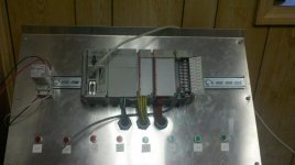
PLC_Trainer.jpg
 

Attachments

  • Analog_Output.pdf
    20.3 KB · Views: 166
Tanner,

What tells the PLC how fast the Powerflex VFD should run? You will need a method to get your speed (frequency) into the PLC.

Wherever the speed reference comes from, move that scaled number to your PLC analog output. This number should be scaled to represent the digital value of your 4-20 miliamp output. Probably all you need is a one of the scaling instruction for that, or use Compute if you want to set up the scaling equations manually.
 
Kandy:

Let´s say that your max speed is 1750 rpm or 100%( 20 mA or 10 VDC), min speed is 0 rpm or 0%(4 mA or o VDC).
You have to use a SCP ( scale with parameter) instruction where output is your analog channel whatever mode you have chosen, i.e engineering value, raw data etc, input must be what you decide to be your value i.e. 0-100% or 0-1750 rpm. The every time you change input output change to the desired speed.
Lancie types faster.
 
Tanner,

What tells the PLC how fast the Powerflex VFD should run? You will need a method to get your speed (frequency) into the PLC.

Wherever the speed reference comes from, move that scaled number to your PLC analog output. This number should be scaled to represent the digital value of your 4-20 miliamp output. Probably all you need is a one of the scaling instruction for that, or use Compute if you want to set up the scaling equations manually.

Lance

I developed a "test" program that widelto is familiar with. In a nut shell there are five conditions:

I have a set of values for these five conditions...
If condition 1, then the value "60" (HZ) is MOVED to tag "Motor_Speed"
If condition 2, then the value 55 is MOVED to tag "Motor_Speed"
If ......... 3, then .........45 ................
if ......... 4, then ..........40 ................
IF ......... 5, then .......... 0 ................

This is the speed refrence tag "Motor_Speed" and I want the value to represent "Hertz"

I am not sure how to scale an output. I have scaled inputs before for example:

I may be reading a large number 605633 at 20mA and 0 at 0mA.
I have always used the CPT instruction to turn this into a percentage, weight measurement etc. But there was always a number that I could see in my controller tag input at the desired point. I just dont see where I am getting an mA output reading. Where should I see this reading?
 
Kandy:

Let´s say that your max speed is 1750 rpm or 100%( 20 mA or 10 VDC), min speed is 0 rpm or 0%(4 mA or o VDC).
You have to use a SCP ( scale with parameter) instruction where output is your analog channel whatever mode you have chosen, i.e engineering value, raw data etc, input must be what you decide to be your value i.e. 0-100% or 0-1750 rpm. The every time you change input output change to the desired speed.
Lancie types faster.

Thanks widelto

Like I was telling Lancie I dont see where I am getting the mA signal. If I could see a 4-20mA somewhere in the program, I could easily scale it. This is where I am stumped. I have just never messed with an analog output before.

Again thanks for your patience
 
just putting the cat amongst the pigeons.
4~20 ma needs to be setup correctly in the PLC.
The analogue card you have is capable of 0-10Vdc.
this is the default setting for the analogue control of the VFD.
Is there a reason for using 4-20 in this application?

- It doesnt really matter which you use but, in the future, when some contractor changes the drive over he will not expect the default dip sw. to be aultered. (stupid not to check I know)

- as far as the scaling - the output is 0~100% so you need to set the VFD to the refference max speed. then you can set the scaling to the min. and your refferenced max.
- the only way you will see the mA output is by inserting a meter in series with the output. - that is why I recommend you rethink and change it back to 0-10 Volt - your choice and the hardware will take it.
 
Kandy show me your plc program I can give you some recommendations about it.

Thanks

I would if I could. I left my PC at the office. I have been in front of it all day trying to figure some things out. I will post it tomorrow morning and you can take a look at it whenever you can. It's basically that same program you looked at yesterday. The one where I needed to add a JSR instruction. This is only a test program by the way. I just want to be able to control the speed of my motor under certain conditions. This is my goal.
 
Ian

Thanks for the reply!

There is no good reason for the 4-20mA switch. I just chose it over the 0-10V for no particular reason.
I can switch the VFD to 0-10V.

You see, my thinking was I could move the value of let's say (60) of the "Motor_Speed" tag to the Local:3:O.Ch0Data and the output point spit out 10V to the VFD input termnial. In this case 60Hz = 10V and 0Hz = 0V. I know how to scale it using a CPT instruction. I just don't know how to change the voltage of my analog card's output terminal. How do you execute this?

I hope I have made myself clear.

Thanks
 
-- here is the difference --
the 0-10v or 4~20 is the reference information only.
you set the effect as a parameter in the drive so 10v or 20mA can be set to a maximum of 60 in the VFD.
NOT PLC dependant.

Now you scale the PLC the output of 4~20 needs to be calibrated to allow for the actual card it is 0~21 mA that is why you need the weird scaling values.
if you use the 0-10v range it is easier to see - although no actual difference.
this is the logical function
[tag for speed] 0~ 60
### scale to 0~100% for output card - this is the same as setting it to 0 - 60 0r 600 if you want more control###
output card give max at 100% output
VFD runs at Maximum preset reference.

I hope that is clearer than mud - sorry if it isnt

EDIT -

Sorry misread your post - usual for me - getting too old

The card has DIP switches be memory on the top (SLC500 sorry)

EDIT 2 - still corrected

in the I/O card setup area for the compact logix sorry
 
Last edited:
Ian

what is weird about this analog card is that when I go to the properties of the analog card, there is no way to scale it. I do not see anywhere to scale it. I will capture some screen shots tomorrow morning and post it.

Your explanation was better and I get it. When I go in the office tomorrow, I will use your instruction.

Thanks again

I will also post the program
 
sorry - you can't scale it - i missled you.
You set the Input and output type 0~20, 4~20, 0~10 etc.
that is what I meant

Scaling has to be done in the program
 
Have you used this formula for scaling.

(Known value - LRV) / SPAN * (URV-LRV) + LRV

I think that is correct.
If you already Know this then disregard.
 

Similar Topics

Hello. I am using the following: Eaton E4-AC-12RXP PLC I am trying to control the CL86T which controls a Closed-Loop Stepper motor. I am using...
Replies
3
Views
957
I had planned to use PTO instructions to control a servo motor, single axis only. We have a ML1200 BWA model. According to the ML1200 manual...
Replies
7
Views
3,464
Can anyone point to documentation indicating which parameters can be changed while the Yakawa P1000 VFD is controlling a motor? I am trying to...
Replies
0
Views
986
Hello, thing that makes me wonder, its the situation when we move axis from one position to other position with CommandTable. For example, after...
Replies
4
Views
1,466
Hi all, I need to control a PMDC motor speed using a PLC. Currently I am using manual potentiometer to do the same. The motor operating voltage...
Replies
5
Views
2,075
Back
Top Bottom