Slow Acting Long Time Interval PID Tuning

The problem is that very few really understand PIDs. ...
Totally agree.

When PLCs began to be able to make floating point calculations I made my own regulation algorithm, one that I really did understand and it worked much better than the previous one.

The previous one worked with integer calculation on the PLC program and was based on a book about PID from the 90s.
The PID is the easy part.
Understanding how the PID works is the easy part.
Understanding how the PID interacts with the plant is not.
A closed loop transfer function is formed by combining the PID transfer function and the open loop transfer function.
Equation 3 in the link I posted above shows how the closed loop transfer function is generated.
Equations 4-11 show how to calculate the symbolic controller gains. Yes, there are formulas for calculating the controller gains.
 
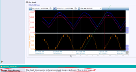
Peter, I do not know where you get a deadtime in hours from!
In the attached image I have added three lines and an elipse. To me, as soon as the cooling valve output is at 0.00% (light brown line I added at 7pm), the Temperature starts climbing. OK maybe not instant, but it is closer to five minutes than the hours-long deadtime Peter suggests.

My next two lines, are light green and red. You see that as soon as the valve opens to 1% at 3:30AM the slope of the temperature starts changing.

The problem is: the valve is completely oversized for the current scenario. The cooling valve needs to sit at maybe 4%?

I would get a proportional valve which is maybe 10x smaller than this one. If you want to be able to control both this scenario, and some other scenario which requires the full output of the existing valve, then you should install two valves in parallel. You could call one ice-ice-baby valve and one daddy-cool.

Playing around with the fact that your valve has maybe 2% play and is non-linear below 10% output is a lot more difficult than measuring the process response and plugging it into a PID tuning constant formula like Cohen Coon!

Three lines and an elipse.png
 
This is an addon to an existing temperature control system. The first system actually had 2 state valves controlling the temperature within a 0.5C deadband, however the large load of glycol shocked the product and was detrimental to the final result and we had to change to a proportional system.


Does that mean the valve being controlled by the PIDE loop is part of the addon system? How long has that addon valve been in place? I.e. what I am getting at is, it possible that it is wire-drawn?


Is the valve severely oversized or is the example trend shown for a case at an atypically low load? If the latter, does the system control better at higher loads?


It seems to me the old system was a 4-state (bang-bang-bang-bang) controller (both valves off, only smaller valve on, only larger valve on, both valve on)*, and it is now an 8-state system (bang-bang-bang-bang-bang-bang-bang-bang) because the valve is limited to integral percentage positions.


Is the load from a batch system or a continuous system (material being added (reactants) and removed (product) at more or less equal rates? What are the inlet and outlet glycol temperatures? Is the outlet glycol usually about the same, or a constant offset from, the tank temperature?


* or perhaps 3-state (bang-bang-bang) with both valves the same size so the two middle states of the 4-state case become one state
 
Trying to keep this response as short as possible...

The Original Poster (OP) provided a lot of good information to start this thread: A trend of the closed-loop response showing the Process Variable (PV), temperature, and Control Variable (CV), valve percent, along with a general description of the process. The controller type [PID], form [PIDE, Dependent Gains], and gain values corresponding to the trend [P=5, I=8, D=1.5] were specified. This is all good, but not ideal for directly computing controller gains to improve performance.

It would be better to have open loop (manual mode) step response trends at one or more valve operating points under disturbance-free conditions. That may not be practical, especially with the apparently long process lag, or even allowable to run in manual mode for long periods of time considering policy, safety, product quality. However, there is enough insight available from the process description and the closed-loop response to make directional moves for controller tuning. One approach to working with the information at hand it to estimate process characteristics and use a tuning strategy (e.g., IMC-based) to compute gains for a desired response.

A very important point, brought up in this thread and others, is that the form of the PID equation in the controller and its engineering units for gains must be known. It may be necessary to convert the computed gains into compatible controller gains; such as whether the form is dependent or independent, and time-related gains are in terms of minutes, seconds, and/or inverse time. The OP specfied almost everything necessary in this regard by stating PIDE-dependent gains. In the context of trend charts showing temperature in degrees and controller output in percent, the missing piece is engineering unit (EU) scaling. This is because Allen-Bradley ControlLogix and PLC-5 (but not SLC) PID instructions expect "unitless" proportional gain, meaning it is in terms of percent-in-over-percent-out. So the PVEUMin and PVEUMax must be applied to EU-computed P gain to convert from temperature to percent. (Technically the same on the CV side, but this is typically in percent, zero to 100, already.)

In the OP's case it turns out the PVEUMin and PVEUMax are also zero to 100, meaning no extra conversion is needed on computing the P gain for PIDE, based on a process gain computed as degrees-per-percent. While this is convenient from a tuning standpoint, it does limit the controller's input range to between zero and 100 degrees.

A couple other follow-up pieces of information from the OP include valve type (ball valve), presence of valve stiction leading to intentional 1% output resolution, and a programmed deadband.

Using all of the OP's information thus far, an effectively tuned PI controller should be sufficient to maintain PV to target with a signficantly tighter tolerance than the current closed-loop oscillation. The disclaimers being: the trend chart only shows a snapshot in time over a relatively small operating window without set point changes or any apparent external disturbances. Nor does it show manual mode operation that may indicate a disturbance causing the oscillation.

All that said, plus previous discussion, the closed-loop behavior implies too much integral and not enough proportional action. IMC-based guidance is to use the process time constant for the integral term with dependent gains in the absence of significant pure deadtime. That is the motivation to increase from 8 minutes to a larger value estimated from the closed-loop response. One could try the phase shift time (~120 minutes) as a starting point, or maybe less if there is concern with such a large change.

On the gain side, I compute an amplitude ratio (AR) of about 0.036 (12.1-11.85/7) at the closed-loop frequency. As noted earlier with the PVEU settings this is already unitless for the A-B PIDE block. Conservative IMC guidance, with no deadtime, is to set P gain at 2 divided by process gain (Kp). If the AR is a good estimate of Kp, that would suggest a P gain up around 100. Since the AR could be attenuated, and that is 20x current P gain, a smaller increase is advised to start with. However, it does need some increase in proportional along with any de-tuning of the integral action, or the loop will become very sluggish or non-responsive.

In summary, one or more open-loop step response tests, up and down, will provide more definitive information than what is inferred from the closed-loop snapshot. In the absence of that, a starting point for incremental tuning is to increase P action and decrease I action. Half way to some IMC-based estimates for the configured PIDE is P=50, I=60, D=0, zero deadband. It would be advantageous to eliminate root cause of the valve stiction and/or reduce the step interval to a smaller effective value (e.g., 0.75% or 0.5%). If these changes improve performance, but short of expectation, make another increment. If possible, force a disturbance or set point change to observe response.

Adding complexity such as feedforward or other features would only be necessary if you are measuring disturbances and want controller action before they affect the PV, or if the deadtime is more significant than implied, or the process operating window moves, or there is asymmetric response or non-linearities. It will take explicit testing to look for these complicating factors, and the best-tuned PI is not meeting performance requirements.
 
Last edited:
I agree with Mispeld and believe he has a good angle on this one, however, it seems strange using PID on heat/cool vessels bang bang control is better, providing the product is being agitated, One thing that is obvious is the oscillation this has to be the Prop component too low, many years ago I was taught by a guy who had spent his life tuning PID's (mainly the old electrical/mechanical types), one sure way is to switch off I&D & give it a good dose of P, reduce P until it becomes unstable, increase the P until stability is improved then introduce the I component, from this it can usually be tinkered with until the required control is achieved, D is rarely used. I was dragged off a project I was doing as another contractor (from a company that supplied & build controllers), he was struggling to get a loop going after an upgrade even though this was his apparent job, the original control was an old Taylor unit (just happened to be one that the engineer who gave me the lesson had previously maintained it), I did exactly as taught & hey presto worked a treat, can't help feeling for the engineer from the controller supplier though.
 
... one sure way is to switch off I&D & give it a good dose of P, reduce P until it becomes unstable, increase the P until stability is improved ...


Wow, my memory is really going, I thought it was the other way 'round: I&D off; increase P until you see stable oscillations (reduce if unstable; "small moves Ellie, small moves"), then reduce P.

Wait, isn't that just a form of empirical Zeigler-Nichols?
 
That's not what I was taught by an old timer & it has worked for me, however, it works both ways so if you start with a small P and gradually increase it is just the opposite way of doing it. the idea is to only put on enough P to make it stable (window) if you like so either way is ok.
So either start with a small or large P, increase or decrease until pass the point of stability, crank it back until stable i.e. find the middle of the best control.
 
...it seems strange using PID on heat/cool vessels bang bang control is better, providing the product is being agitated,...


OP said bang-bang-bang(-bang?) control shocked the product, so maybe improving agitation would have been a better choice of project than the PIDE addon, but that horse has already left the stable.


Just thinking out loud (i.e. another country heard from)


Another way to do this would be to raise the temperature of the chilled glycol to reduce the process gain; it would not affect the tuning other than changing the final Kp, but at a minimum it would allow a less discrete set of available integral-percentage CV values; by reducing shock it may even make bang-bang control a feasible solution. It would cost more for pumping energy, while the cooling/chilling cost would (should?) remain the same.


Looking at the data, I agree with @Mispeld and @AustralIan that there deadtime is small here (5 minutes max), in any event much smaller than a lag that appears to be of order 1-3h. And that makes sense: heat transfer coefficient goes with flow to the 0.8, IIRC; then it's conduction/convection to the temperature sensor; the change of steady-state temperature difference with flow takes a bit more, but that is likely a small part of this. So I would expect that, to first order, the response of the temperature sensor to a change in flow is more or less immediate compared to the lag.


I am still suspicious about a "temperature sensor ... located between the two [cooling?] jacket rings" - the temperature of material being actively cooled is a, shall we say, less than ideal proxy for the temperature of the material in the tank, not that measuring temperature in a tank exactly easy in the first place. But again, that is likely another horse that has left the stable.


In the end, this is (analogous to) a vessel level control with a control valve emptying from the bottom: heat is the analogue for fluid; temperature measurement is the analogue for the level measurement (PV); the process is adding heat~temperature) (fluid~level) at some rate; the control valve (CV) is removing heat~temperature (fluid~level) at some rate, when the temperature is steady there is no accumulation and the temperature (level) will be constant. The process gain is not linear, but sides of the vessel are probably close enough to vertical.
 
Last edited:
Yep, but I'm an old timer, so it sticks. couldn't care if they are called sausages I know what I mean lol. There is no difference if the in vs out is reciprocal, however, if it is not then yes there is a difference in the setting but if tuning by adjusting whether it is called band or gain does not matter.
Just an update on my last post, Yes I would probably start with a small P if it was a bit dicey having the output going to full very quickly, however, most of my PID tuning has been on steam injection or Heat Exchangers, so no problem, certainly if I was in doubt about any danger of a problem I would do it this way,
perhaps I have been doing this a long time & generally get it close from the initial settings of P by experience, I generally bring it down until oscillation then find the mid point this way you know it is not on the "EDGE" if you know what I mean.
 
"By an old timer" may be the key to this disagreement. In the OLD days "P" was proportional band ( pneumatic controllers)...


d'Oh! My second today. Of course @parky was right, I should have spent time to think/remember more.


Thanks @Mickey.
 
Last edited:
DR: I must have missed the bit about the temp probe not being in the product, never heard of that before really weird that, I once did a system where the control was specified using Eurotherm controllers for the heating loops, these were pressure not temperature but the measured variable was temperature (customer requirement). we would send a 4-20ma signal to the controllers for the temperature set-point, however, most of the products produced in the vessels was quite thixotropic, the problem was that as the product thickened the steam injectors (this was direct injection into product) would blow holes through the product wasting the energy & the temperature would not rise to set-point. So the temperature controllers would see the slow down, increase the steam pressure, a vicious circle, These vessels were shallow, and to stop breakdown of the particulates in the sauce the agitators were very slow.
I had to do a quick think solution so I bypassed the controllers & had a lookup table for temperature and just pushed out a pressure setting vs temperature, so in essence the system would start at full pressure until a certain temperature then change to the next lower setting, this was done until the temperature reached within a couple of degrees of set-point then a simple PI control I wrote took over. worked a treat.
This gave me an idea, perhaps put force the PID into a manual mode, adjust the output of the PID to set values depending temperature, then x degrees before set point switch over to auto, I have done this in the past where cold water was injected into a control loop, the sudden change upset the control.
Basically When the cold water valve opened I set the PID to manual, set the output to a set level, when the temperature rose to about 5 degrees below set-point, switched it back to auto, the reason for this is we wanted the heating loop to heat the water as quickly as possible so that the storage tank water temperature would not fall below a certain level. There was two main problems, the water temperature was to be maintained at 98.0 degrees, putting cold water into the tank caused cold spots, the heating loop struggled to cope, injecting it into the re-circulation loop reduced this effect but took time to get back into control and would overshoot just enough to produce steam rather than hot water, by forcing the MV to a set value i.e. nearly 90% this put plenty of heat into the cold water, switching back to auto meant no overshoot. The idea was to maintain a nearly full tank of hot water so this injection of cold water (when the process that required it was running) happened frequently not too much to cool the holding tank but enough to keep it pretty full.
 
On the gain side, I compute an amplitude ratio (AR) of about 0.036 (12.1-11.85/7) at the closed-loop frequency.

Bottom line: OP should try @Mispeld's tuning.


TL;DR

I think that AR may be off, but only a bit. We have the gain in front of us: the process is adding temperature (~heat) at a variable rate, the control valve is also removing same at a variable rate, but when the temperature is at a value at time Tstart, and returns that same value at time Tend, then the heat added by the process is equal to the heat removed by the control valve (to first order and assuming a batch process). So isn't the ratio of the areas under the curves the actual amplitude ratio?


My calibrated eyeball informs me that both PV and CV curves are sine curves going from 0 to PI. The area under a +/-1 amplitude sine curve from 0 to PI is 2, so scale the peak-to-peak by 2: PV=(12.1-11.85)*2 = 0.5; CV = (7-0)*2 = 14. One twist: CV goes from 0 up and back to 0 in the latter 70% of the time that the PV goes from valley to valley, so scale CV by 0.7 14*0.7 ~ 10. So an alternate AR is 0.5/10 = 0.05, which changes essentially nothing about @Mispeld's back of the envelope analysis; I just brought in an additional envelope.


Caveat: the control element is a ball valvem OP said they put a non-linear response between the PID and the physical valve at low percentages, heat removal is proportional to flow**0.8, etc. so the temperature effect of CV is non-linear and that affects both AR estmates. But meh.
 

Similar Topics

Hey guys, I have a Controllogix and I am tying to control a PID loop for Chlorine (CL2). The trouble is the mixing point is 15 minutes away from...
Replies
16
Views
6,752
Anyone have issues with RSLinx being very slow to open. It sometimes will say "Checking Activation" at the bottom for what seems like an...
Replies
2
Views
132
Hi All, we've recently upgraded from FTView SE v10 to v12. Since the upgrade we've been having a problem where the HMI is slow to update tags in...
Replies
0
Views
87
Hi, I have some problem with View Point which I'm using to manual control of conveyors. On begin when in network was only PLC and HMI View Point...
Replies
0
Views
69
Hi. Importing a 2014 aapck in 2023: no problem using it, adding windows, works very well, no problem whatsoever. Creating a new project: as...
Replies
2
Views
741
Back
Top Bottom