HMI Vijeo and DF1 from Micrologix 1400

Wiktor

Member
Join Date
Nov 2012
Location
Katowice
Posts
13
Hi,

I have problem with communication between HMISTU655 and Micrologix1400.
HMI is connected by COM1 to channel2 of micrologix, channel1 it's used for other comm.

Did someone connect HMISTU to ML1400?
In documentation form vijeo "Allen-Bradley DF1-Full Duplex Driver" is only ML1000, 1200, 1500, so it's mean 1400 it's not compatibly? I hope that it's old document thats why 1100 and 1400 are not in list.

Welcome to the Forum!

The ML1400 should be fine with DF1. Make sure that the ML1400 Serial Channel 2 is set for DF1, and that the PLC and HMI Baud Rates and Error Correction match. Be aware that there are variations in the DF1 Protocol between the PLC5 and SLC/ML lines. So, you have to make sure that the HMI and PLC are using the same Parameters.

What are you using for a Serial Cable between the HMI and PLC?

Stu....

Divers in HMI are chosen AB/micrologix/DF1, so it's not mixt with PLC5 or others protocol (separate drivers).

DF1 speed, parity, crc are identical in PLC and HMI.
Cable: home made D-SUB9 to RJ45. Quality control pass :)
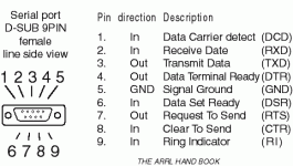
PLC D-SUB have standard pin out (dsub9.gif) ?
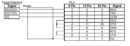
I attached also 2 files with HMI pin out (form HMI doc.)

PLC HMI pinout connection DF1 full duplex.jpg HMI COM1 pinout.jpg dsub9.gif
 
Divers in HMI are chosen AB/micrologix/DF1, so it's not mixt with PLC5 or others protocol (separate drivers).

DF1 speed, parity, crc are identical in PLC and HMI.
Cable: home made D-SUB9 to RJ45. Quality control pass :)
PLC D-SUB have standard pin out (dsub9.gif) ?
I attached also 2 files with HMI pin out (form HMI doc.)


Well, it all looks reasonable. According to the Diagrams, it should just be RXD, TXD, and SG. From the Diagrams you Posted, it would be easy to confuse the RXD, and TXD Pins.

If I am understanding the Diagrams correctly, Pin 1 of the HMI (RXD) goes to Pin 3 of the PLC (TXD), Pin 2 of the HMI (TXD) goes to Pin 2 of the PLC (RXD), Pin 8 of the HMI (SG) goest to Pin 5 of the PLC (SG).

Is that the way you see it?

Stu....
 
Problem solved by using Ethernet port!
I start form DF1 because I find in vijeo doc information that for Ethernet (ML1000, 1100, 1200, 1500)I need 1761-NET-ENI
No any info about ML1400, so I try to connect and it's work fine!

Finally ML1400 works fine with vijeo 5.1 drivers AllenBradleyEtherNetIP01 EIPMicroLogix01.
Problems with DF1 com on port3 not solved.

I try with ML1100 and... Ethernet connection works without 1761-NET-ENI !
Probably because of new FW (I have SER:B, REV:E, FRN:11)

I am glad you have it working. I believe it should communicate with the ML1400 without problem, regardless of the Firmware Version. Other than the differences I mentioned in the earlier Post, DF1 should be DF1. Hopefully Ken Roach will chime in if he has time.

Stu....
 
...the ML1400 without problem, regardless of the Firmware Version. ..
Stu....

ML1400: no any info about this model in Vijeo documentation.
ML1100: according Vijeo 5.1 doc need 1761-NET-ENI for Ethernet connection (more expensive than ML1100 itself!). I think when Schneider El. wrote this information because ML1100 was available with older FRN who not support Ethernet connection to HMI, or something like that.
Now on ML1100/FRN 11 connection works fine.
 
Hi, If I may chime in...

Wiktor, I'm glad you realised that Ethernet is the best way to communicate between these 2 devices and are now up & running. I too use ML1400's with HMISTU655's & HMISTU855's, nice HMI.

Having read the thread, I felt it needed closure.
This is to assist others who may want, or have to use either DH485 or DF1 for ML1400 CH2(D-SUB9) to COM1(RJ45) on a HMISTO/STU & need to make a cable. It's not difficult, if you follow Schneiders driver help docs carefully, but some may get confused between the many wiring options they give as to which one to use. There is a little bonus too.

It's fairly comprehensive, so if someone feels this should be a "How To" posted somewhere else, please move it or ask me to post it seperately instead.

I had originally tried the ML1400 with the lesser, serial only, HMISTO511. Initially I used DH485 for that setup and made my own cable from the driver help file doc.

DH485 Cable: (ML1400 Ch2 D-SUB9>HMISTO/STU COM1 RJ45)
Page 14 of Schneiders "Allen-Bradley DH485 Duplex Driver" doc (attached below) shows the wiring options for COM1(RJ45) as RS-232C or RS-232C.
The top pinout is indeed RS-232C, but the bottom pinout is RS-422/485, it's a typo error. We are using RS-232C here.
So from this we use pin 1-RD(RXD), pin 2-SD(TXD) & pin 8-GND.
Now go to page 16. Here we use "b.Connection Diagram". Notice the CS/RS link on the target side & the note below. Ignore this link for STO/STU's, as it is only relevant to higher model Magelis HMI that have D-SUB9 COM ports.
In this diagram they do not show pin numbers on the target side as it relates to many different HMI models, which differ in port types & pinout numbering.
For reference, write "8" beside "GND", "2" beside "SD(TXD)" & "1" beside RD(RXD).
This is important! The diagram shows the D-SUB9 plug wiring intended for a NET-AIC. The ML1400 can connect directly to the HMI, if you don't have a NET-AIC. However, Ch2 on the ML1400 is a non-isolated port. The NET-AIC's ports are electrically isolated from each other & so it provides protection against ground loops & voltage differences between the devices connected to it. Connect without NET-AIC at your own risk!
The D-SUB9 standard pinout diagram was linked by Wiktor earlier, so I wont attach it again.
Now you should be ready to make your cable.
Once cable is ready you have to setup your equipment port & driver settings.
Setup Ch2 on ML1400 for Driver: DH485, Baud: 19,200, Node Address: 1
(or whatever Node number your PLC is assigned on your network).
In your Vijeo Designer project scroll down to "IO Manager" & right click then "New Driver". Select Manufacturer "Rockwell Automation", then from left list choose "Allen-Bradley DH485, then from right list choose "DH485 MicroLogix". A new driver is created under "IO Manager" named "AllenBradleyDH48501 [ COM1 ]", double click this. In the Driver Configuration window set connection type: RS-232C, trans speed: 19,200 & node number: 2
(or whatever Node number your HMI is assigned on your network).
Now expand "AllenBradleyDH48501 [ COM1 ]" & you should see your equipment "DH485MicroLogix01". Double click & you get Equipment Configuration window. Set your PLC's node number here: 1 (or whatever).
Don't forget to select "DH485MicroLogix01" as the "Scan Group" for each variable you create(d) or they will not work.
Now you have configured your DH485 driver & equipment in Vijeo Designer ready for download to the HMI.
Once the RSLogix 500 & Vijeo Designer projects are loaded to the equipment, plug in the cable & test your comms status at the PLC. You should see the COMM 2 indicator on the LCD display on steady. Online, check the comms status & you should see messages sent/received totals are active for Ch2. If you have any I/O to the HMI panels, they should be active now also.

DF1 Cable: (Here comes the bonus!)
The DH485 cable will also work for DF1, so no need to make a second cable!
Only differences are:
Set ML1400 Ch2 for DF1 & setup the new DF1 driver in Vijeo. The default settings for both are fine.
Don't forget to change the "Scan Group" for variables to the DF1 driver.
When testing, the COMM 2 indicator on LCD display will blink when comms are active.
Note: DF1 will also work with or without NET-AIC.

Because I chose to test DH485 initially I hadn't read the driver help file for DF1. I just tried the DH485 cable for DF1 after DH485 had worked & DF1 worked first time. But when I saw your diagram from the DF1 help file Wiktor, I noticed something straight away!

sthompson wrote:
From the Diagrams you Posted, it would be easy to confuse the RXD, and TXD Pins.

If I am understanding the Diagrams correctly, Pin 1 of the HMI (RXD) goes to Pin 3 of the PLC (TXD), Pin 2 of the HMI (TXD) goes to Pin 2 of the PLC (RXD), Pin 8 of the HMI (SG) goest to Pin 5 of the PLC (SG).
Is that the way you see it?

It would be even easier to confuse the RXD and TXD when the diagram is incorrect! Wiktor, you didn't answer the question as to how you saw it when you went to wire it up? If you followed Schneiders diagram it would never have worked as they show HMI pin1(RXD)> PLC pin2(RXD) & HMI pin2(TXD)> PLC pin3(TXD). Yet another typo. I've attached a corrected version of your earlier diagram. It's all academic beyond "The DH485 cable will also work for DF1, so no need to make a second cable!", but its always nice to get to the bottom of problems for everyone's benefit.

Geospark.
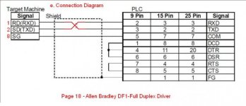
PLC HMI pinout connection DF1 full duplex(Corrected).jpg
 

Attachments

  • RockwellDH485e.pdf
    212.6 KB · Views: 77
  • RockwellDF1FullDupe.pdf
    211.9 KB · Views: 99
Last edited:
Thanks for explanation Geospark!
I made wrong cable according Schneider diagram! I look only on pin no not TX/RX description :(
BTW It is some way to import variables form RSlogix to Vijeo?

Geospark, you use RSLogix 500 for ML1xxx? I have RSLogix micro, local AB says that for ML1xxx I must use RSLogix micro, not 500 or 5000.
 
I'll handle the software question first. From my experience of the different versions, here is what I know. If I'm incorrect someone please correct me. I know most users know alot of this already, but I like to post for the benefit of others searching for this kind of info. It may already be here somewhere I'm sure.

From Rockwell Documentation:
What is RSLogix Micro?
More cost-effective application development software exclusively for Rockwell Automation MicroLogix Controller customers
Same reference standard features as RSLogix 500, but simplified by
No SLC controller support
No FactoryTalk Services support (except Activation)
Standard Node-locked license only
Smaller footprint install of RSLinx Classic
Support of On-line (run mode) editing for all MicroLogix that support it
Readily shares project files with RSLogix 500
Cannot be installed on same PC as RSLogix 500

The difference between the Micro editions is which controllers, or features of controllers, they support.
Some might mistake the "Micro" in the software description as meaning a lesser featured version of RSLogix 500. In truth it is, but the "Micro" just refers to the MicroLogix Controller Family, as that is all the RSLogix Micro editions support.

"RSLogix Micro Starter Lite" is the minimum edition you can use and is free to download. It replaced "RSLogix 500 Starter Lite". This edition only supports the Micrologix 1000 and 1100. The 1100 allows online editing and Lite supports this feature, but you must download "RSLinx Lite" to use this feature.​


You can use RSLogix Micro "Starter" or "Developer" for all of the MicroLogix Controller family(1000,1100,1200,1400,1500). They are not free. They also support online editing, which the 1100 and 1400 support. So if you use 1400's and want online editing, you must use at least "Micro Starter" edition.
"Starter" edition would probably be ok for most MicroLogix only users.​

This is a small doc on RSLogix Micro. There is a "Starter" & "Developer" edition supported features list at the end.
http://literature.rockwellautomation.com/idc/groups/literature/documents/pp/9324m-pp001_-en-p.pdf

"RSLogix 500" adds features to the above, such as SLC500 Family Controller support and comes with the following editions:
"RSLogix 500 Starter"
"RSLogix 500 Standard"
"RSLogix 500 Professional"​

I won't go into all the differences between them, you can check them out here:
http://literature.rockwellautomation.com/idc/groups/literature/documents/pp/lg500-pp001_-en-e.pdf

Again, "Starter" would probably do most users, but only supports online editing for the MicroLogix 1100 and 1400. "Standard" adds on SLC500's to this.​

Wiktor, I don't know what version you have, but RSLogix Micro is fine for the 1100 and 1400 you've mentioned using earlier. We, however, use "RSLogix 500 Standard" and the reason is that we have SLC503's and SLC505's as well as MicroLogix Controllers and do use online editing, online cross reference etc.​

I'll post another reply on the variables export/import question later.​

Geospark.​
 
Sorry Wiktor, I have been busy renovating an en-suite! & tackling some Point I/O issues in work that has tied me up alot :cry: I haven't forgotten you. I don't like rushing replies that require detail, documents, links etc. I have finished both jobs now so I'll post you a reply later when I'm in work where I have the resources to help. Might not be all good news though :oops:

G.
 

Similar Topics

Hi, I have Schneider MTZ circuit breaker giving Energy value in int64 format (volts,amps etc are in FLOAT) What options do I have to display...
Replies
1
Views
1,276
I'm building a test station for water pumps. The HMI will display GPM, KWh, pressure, vacuum and speed. Client currently manually writes down...
Replies
9
Views
4,988
Hi all, I'm very new to HMI's and totally new to Vijeo. I've been given the task of helping a company upgrade their Vijeo HMI's from Windows XP...
Replies
5
Views
5,016
Dear All, Is it possible to replace a variables in vijeo desiger like other HMI software by find replace variables to save time. let's say that a...
Replies
19
Views
20,920
Hi guys! I encountered an error on vijeo citect HMI. The system is configured as main and standby HMI. I have this error on standby HMI, "ERROR...
Replies
1
Views
6,907
Back
Top Bottom