Another Analogue Input Problem (Sorry) Omron CX-Programmer

sovad

Member
Join Date
Sep 2012
Location
melbourne
Posts
6
Hi there,

PLC in question: 240VAC Omron CP1E-NA20DR-A
Features: 12 inputs – 2 of which analogue, 8 outputs – 1 of which analogue

My question is in regards to using an analogue input.

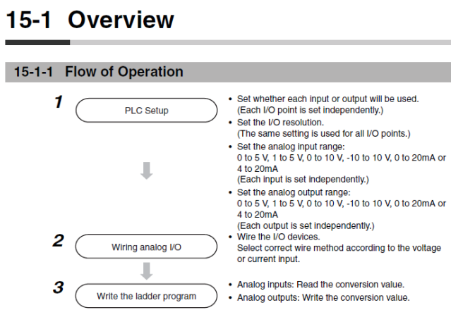
Starting with the manual procedure for installing an analogue input:
Pic1.png


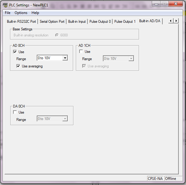
1) So I began with setting up the analogue input; AD 0CH, Range 0 – 10V, Use averaging (as suggested):
Pic2.png


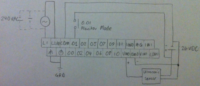
2) Wire up device, this is my current wiring diagram:
Pic3.png


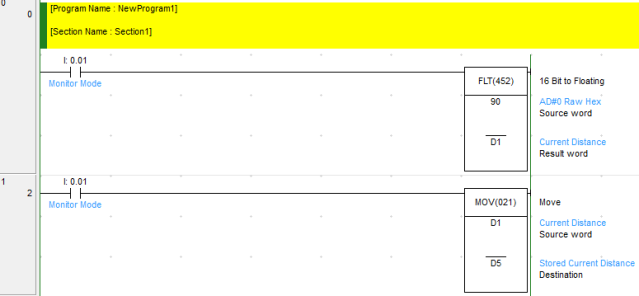
3) Write the ladder diagram, I have a more sophisticated program prepared but I thought I’d simplify things in order to check everything is working properly:
Pic4.png


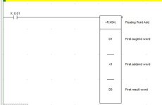
In this program I am trying to read an analogue input from an ultrasonic sensor with a 0 – 10 VDC output (AD#0 Raw Hex) and convert it to floating point so I can do additional arithmetic. The source word address should be correct as it specifies in the manual that AD0 data is stored in CIO 90. Then I want to store this initial reading in memory D5.

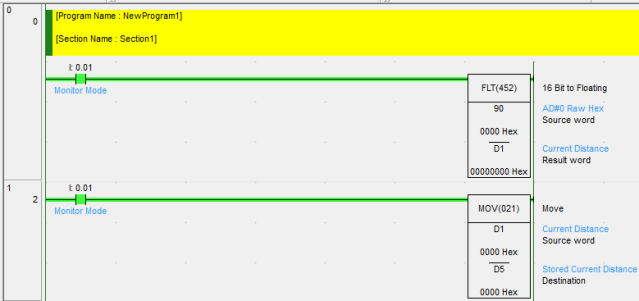
This is what the program looks like when it is running:
Pic5.png


As you can see the source word is 0000 Hex but it should have a reading between #0000 and #FFFF. I have checked the ultrasonic sensors output with a multimeter and I do get a reading between 0 and 10.25 VDC depending on the distance.

I have tried a number of things to make this work but I’m out of ideas. If you have any suggestions as to what’s going on and why this is not working please let me know.

Thanks in advance
 
Another thing - conversion will not take place unless the PLC is in run or monitor mode.
 
The input led is not lighting up when the analogue input is connected, I don't know if that helps but I would think it should light up upon applying a voltage.
 
You need to transfer the analogue configuration settings from the PLC settings screen as per your first post.
I always set the mode to monitor in settings as well before downloading to the PLC as if the PLC is re-powered it will then run in monitor mode and allow online programming changes.
 
The input led is not lighting up when the analogue input is connected,...
As you can see the source word is 0000 Hex but it should have a reading between #0000 and #FFFF.
These are indicators that your analog input is not connected correctly to the PLC (or is not working but you tested for that). Double-check your wiring instructions for the ultrasonic sensor. You could have 2 of the 3 wires switched. Make sure that the Ultrasonic sensor +Vin terminal has not accidently got swapped with +Signal Out.
 
Last edited:
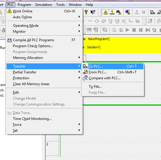
If this is what you mean by transfer Bob

Pic6.png


Thanks anyway
After you select "transfer", another screen will pop up with a list of what to transfer. Be sure that the "settings" check box is selected. After you do the settings transfer, you must cycle power to the PLC before the settings will take effect.
 
Hi there,

I have checked that the settings are being transferred through both the setting screen and the PLC transfer sub menu. I have also done a transfer from the PLC and the settings have been changed. After any changes I always turn the PLC off then on again. As for the wiring, I'm quite sure it is correct because I have been checking the voltage output at the PLC terminals and I do get a change in voltage between 0 - 10 VDC depending on the distance.

I'm not sure if it is an addressing issue or some settings issue or what really. It seems that the analogue input on the PLC is just not activated.

Thanks again
 
Post a shot of your I/O table - that will show the addressing.
Also enable 'break detection' for the input and if there is a perceived break the error light will come on on the card.
 
I got it working. I'm not sure exactly what it was but I re did everything from scratch and it starting working (yes!). One thing I did notice though was that the MOV function does not work how I thought. I thought it moved and stored a word in a particular location in memory until told otherwise but instead it only moves the location. I think this can be changed by putting an @ symbol in front of it but it was just something I noticed.

Thank you for your time everyone, it's good knowing I have some back up.
 
You cannot use the move function for floating point values in the CP1E.
The MOVF (which would be perfect) is not available in the CP1E instruction set.o_O

The best way I have found is to use the floating point ADD function and add the value of 0 to store the variable in a new loacation.

Capture.JPG

Hope this helps.
 
These are indicators that your analog input is not connected correctly to the PLC (or is not working but you tested for that). Double-check your wiring instructions for the ultrasonic sensor. You could have 2 of the 3 wires switched. Make sure that the Ultrasonic sensor +Vin terminal has not accidently got swapped with +Signal Out.
this is the same problem with me lancie :mad:
 

Similar Topics

Hi, The hardware is: Click Plc model # CO-O1DD1-O HMI model # S3ML-R magnetic-inductive flow meter model # FMM100-1001. I will set the flow meter...
Replies
4
Views
90
So I had an odd request from a customer for the above. I have written the logic and tested it all in one PLC with only using 7 outputs and 7...
Replies
15
Views
402
Hello I need to message read the entire 16 channel raw analog inputs from a 1769-L33ER Compact Logic controller to another 1769-L33ER Compact...
Replies
8
Views
239
I am noticing a problem where i am using MOV instruction and writing literal text into source and String datatype in destination. It works fines...
Replies
6
Views
445
I'm not actually in front of the equipment yet, but this is the information that I have been given by a client: ------------ Data from HART...
Replies
2
Views
326
Back
Top Bottom