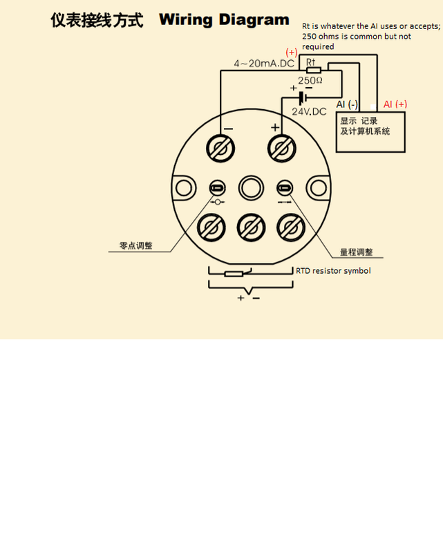
Why a resistor? problem with the diagram
Why a resistor?
All electrical current measurements (except for analog moving coil galvanometers) are actually voltage measurements - current flows through a resistor creating a voltage drop which is then measured by the amplifier-A/D combo.
Sometimes the resistor is built into the analog input, sometimes it is not and is an external resistor.
Most PLC's seem to use 4-20mA AI modules with internal resistors, so an external would not be used with an AI that already has an internal resistor.
But not all 4-20mA AI modules use internal resistors.
The original drawing derives from the 'external' resistor genre.
I suspect that use of an external resistor comes from the DCS world because the DCS world drove the development of the two-wire loop-powered 4-20mA signal. DCS's deal with hundreds, if not thousands of 4-20mA loop signals coming into marshalling panels. DCS systems originally used large 24Vdc power supplies to power dozens of loops from one power supply.
If there is short circuit in the pair of any loop's "two-wire" field wiring, that short circuit puts 24V (+) on the one conductor directly on the conductor running to the Analog input's (+) terminal. The input's dropping resistor then has the full 24Vdc power supply potential across it. The input resistor burns up.
The dreaded Ohm's Law tells us that 24V across 250 Ohm resistor produces 96mA of current. 96mA of current at 24Vdc is 2.3 watts. The resistor is probably a 1/4W or maybe 1/3W resistor if it is external, but is more likely an 1/8W resistor if it is internal. Regardless, 2.3W will rapidly heat up and burn out even a 1/2W resistor.
If the burned out resistor is external, then the burned out resistor is the only damage and replacement is relatively easy because it is external, connected to the wiring terminals.
If the burned out resistor is internal, inside the AI module/card, then that channel is toast. Repair involves a costly DCS input board/module.
Since DCS's deal with hundreds and thousands of loops, a DCS might experience field shorts and view the external resistor as a means of protecting the AI cards/modules from field short circuits.
Problem with the diagram
The polarity of the connections at the analog input are backwards on the original drawing.
The power supply (+), by convention, connects to the (+) terminal on the field transmitter.
The field transmitter's (-) then connects to the analog input's (+) terminal.
Whether the resistor is internal or external, the field transmitter's (-) terminal connects to the AI's (+) terminal. That is not case in the original diagram where the field transmitter's (-) terminal connects to the (-) terminal on the AI (-).
Dan