Is it possible to program this onto a Click PLC? If so, I need help anyway.

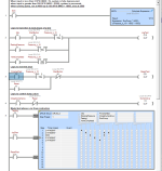
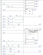
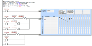
There is an instruction called a drum in AD software. Here it is in DoMore; I would think Click would be similar, but who knows. All it does is trade @parky's several [if step=N and (step N complete) then step = {step + 10}] sequence transition rungs for a behemoth of an instruction.

It does save a few rungs for setting outputs.

It does not have the pass-fail logic, and I am assuming the input raw WX0 16-bit integer is pressure in dPSI, so it will not be any shorter than @parky's in the end.

There is a bug when the DoMore simulator starts, in that for some reason C3 seems to start with an initial value of 1, which jogs the Drum to Step 2. I have not been able to figure out why, so if anyone can give me a hint; I am loathe to think it's a bug in the simulator.

But once the drum either completes a cycle or has been reset, then it runs as expected.
Untitled.png
 
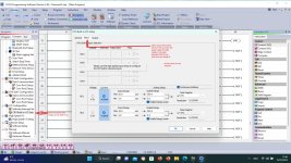
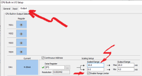
Just incase you are struggling, below is a pic of how to setup the analogs
On the left navigation pane select the tab for Function then click the I/O configuration & select Built in I/O
In the popup select input and at the bottom are the analog inputs, select 4-20ma for both channels, change the scaled range to what ever your transducer is, you do not have to change the pre-populated registers it defaults to DF1 & DF2 (they can be changed but why bother) these are floating point (real) registers, click on the output & do the same for the analog outputs I suggest the scaled range be 0-100.0 (for %) this is standard as if this was a PID fed it makes sense all it means is you are driving the I/P (4-20 ma) at 0-100% so when you send the flow setpoint to the I/P (motor).
just so you know.
X are inputs
Y are outputs
C are internal Bits to use in program
T are timers
CT are counters
DS are 16 bit registers (integers)
DD are 32 bit registers (long integers or double integers)
DH are 16bit hex registers
DF are floating point (32 bit) registers
SD are system data registers (used for information i.e coms status etc.
SC are system control bits, these contain things like always true bit one scan on start up, clock bits like 10ms clock, 10ms clock, 1 sec clock etc.
SC & SD have symbols already so tell you what they are.
If you click on the address picker from the top menu (press home button first) it brings up a popup where you can edit the symbols (descriptions)of what all the I/O, registers etc. you are using are.

Clck PLC config.jpg
 
Most PLCs can be programmed using a standard computer and PLC programming software. The International Electrical Code's IEC 61131-3 standard defines five languages for PLC programming.
 
I was able to workaround my DoMore bug by adding a Run input (X2) that resets the drum whenever it is off, so even though C3 comes on for some reason when the simulator starts, it is reset in the drum.
 
Yeah, used a drum sequencer on another platform did not like it limited steps, on that one could not step back & TBH it took more processor time than rolling your own, but that is probably because of the different functions.
The only other one I came across was in Siemens S5, it was a sort of drum sequencer it was not built in but a add on function, I managed to open it up & look at the MC5 code, again it was quite large the engineers at that site hated it as they did not understand it, found it difficult to follow Mitsubishi have SFC again step transition is hard to follow if you did not program it, most engineers I know hated it.
 
@drbitboy @parky Hello I am back from the weekend. Time to get to work. I will read all the things you guys posted. It seems like you guys really want to help, I really appreciate it. I will do some more learning from what you recommend and also the codes you posted. I have skimmed through them, and it all makes sense to me so hopefully I can get something out of this week. I am planning to learn more about the electrical side of the PLC. If I don't know how everything connects then how will I know what PLC to get, so that's why I will focus on that. Also, I will give you my parts list I made already if you two want to skim over it.

NCP2-20-3120N ( pressure transducer, current to pneumatic transducer)- https://www.automationdirect.com/ad...o_pneumatic_(i-z-p)_transducers/ncp1-20-3120n

SPT25-20-2000A (pressure transmitter)- https://www.automationdirect.com/ad..._sensors/pressure_transmitters/spt25-20-2000a

EA9-T6CL-R (hmi touchscreen)-https://www.automationdirect.com/adc/shopping/catalog/hmi_(human_machine_interface)/c-more_touch_panels_ea9_series/c-more_ea9_series_touch_panels/ea9-t6cl-r

PARKER GRESEN Pressure Relief Valve: 0 to 2000 psi (mechanical relief valve)-https://www.grainger.com/product/38D924?gucid=N:N:pS:paid:MS:CSM-2295:TVRYAD:20501231&gclid=9335421c701c1e763b3f21dc7e0b7dd5&gclsrc=3p.ds&gclid=9335421c701c1e763b3f21dc7e0b7dd5&gclsrc=3p.ds&msclkid=9335421c701c1e763b3f21dc7e0b7dd5

Solenoid Valve: 1/4 in Pipe Size - Valves, 120V AC, 0 psi Min. Op Pressure Differential- https://www.grainger.com/product/REDHAT-Solenoid-Valve-1-4-in-Pipe-6WTT0

Click C0-12DRE-1-D- https://www.automationdirect.com/ad...stackable_micro_brick)/plc_units/c0-12dre-1-d

Click Power Supply C0-00AC- https://www.automationdirect.com/ad...ackable_micro_modular)/power_supplies/c0-00ac

Serial to RJ-12 cable for hmi- https://www.automationdirect.com/ad..._panel_-a-_micro-graphic_panel_cables/ea-2cbl
 
Last edited:
Yeah, used a drum sequencer on another platform did not like it ... most engineers I know hated it.


I agree: your step coding is easier to follow and debug.

I did it because the drum satisfies my "code golf" bent. It will do less so without hard-coded pressure levels and pump speeds.


This is a simple sequence, so drum might work for OP; it seemed worth presenting all the options.
 
Hello. I figured out how our pump system works when doing manual testing. Here is the basic diagram I made.

https://imgur.com/a/wuwJs35


There is a compressor that has a constant 140psi pressure of pneumatic air that is fed into the pump system. The first pressure gauge also has a manual knob on it to let the compressed air into the pump. As the pump starts building pressure it builds pressure in the water at the outlet of the pump.
I think that the current to pneumatic transducer will work, but couldn't I just use a solenoid valve or some sort of electronic control valve instead of the transducer?
Not sure if that would be a great idea because the transducer can accurately give out a certain amount of pressure while the valve can be open halfway and we don't know how much pressure is being let it.
 
Last edited:
I will try to recreate Parky's type of code into click programming software. I will see how it goes and post my results here


Good idea. That will allow you to partition the code for each section and make it easier to understand.

Btw, you never answered this:

What does the operator's manual "knob" vary? Will the PLC's analog output to the electric-to-pneumatic transducer control the same thing as the knob?
[The rest of this may be moot, depending what the manual knob controls, but I already had this mostly written]

It sounds like the I-to-P is the same as the manual knob i.e. a pressure regulator, and the air-driven pump will stop moving liquid into the test part when it stalls i.e. when the regulated air pressure to the air-driven pump is the water pressure divided by the pump's pressure ratio (minus some frictional ε).

If that is the case, and assuming the pressure rise is slow enough, I suggest a simple proportional control algorithm:

  • Configure the Analog Output channel
    • to have 0-10 (PSI) in the scaled range,
    • correspond to 4-20mA in the Output Range
    • And use a REAL Data Register, e.g. DF5, with a nickname RegulatorOut.
    • So like this:
      Untitled.png
  • Then, in the program:
    • Take the HMI target pressure, PHMI, e.g. 200PSI, and add that pad from the AO channel configuration say 10, via a Math instruction:
      • Result: a REAL Data Register e.g. DF10, with a nickname PHMIplus10
      • Formula: PHMI + 10.0
    • Take the measured pressure, Pmeasured, rises, subtract it from PHMIplus10, in another Math instruction
      • Result: a REAL Data Register, e.g. DF11, with a nickname Pdelta
      • Formula: PHMIplus10 - Pmeasured
  • Use two rungs with Math instructions to write the AO channel value RegulatorOut (DF5; AO channel Data Register from AO configuration above)
    • First rung, unconditional Math instruction:
      • Result: RegulatorOut
      • Formula: 0.0
      • This will write a 0 to the AO channel any time the pump should not be running
    • Second rung, conditional Math instruction:
      • Rung Condition: [Sequence Step] = 10
        • the sequence is at Step 10
        • pressurizing, pump running, solenoid valve closed)
      • Math Result: RegulatorOut
      • Formula: PHMIplus10 - Pmeasured
Say PHMI is 200PSI, the pad is 10PSI, so PHMIplus10 is 210PSI:

  • At measured pressures (Pmeasured) below 200PSI, RegulatorOut (= PHMIplus10 - Pmeasured) will be greater than 10,
    • So the AO channel Range Limiter (enabled in the config menu) will limit the output signal to 20mA,
    • the regulated pressure to the air-driven pump will be the same as the nominal supply, and
    • the pump will increase the measured pressure over time
  • At measured pressures from 200PSI up to 210PSI, RegulatorOut will vary from 10 down to 0,
    • So the AO channel output signal will vary from 20mA down to 4mA,
    • the regulated pressure to the air-driven pump will start dropping,
    • but the pump will keep running and increasing the measured pressure,
    • until at some point the air-driven pump will stall,
    • which stall will occur before Pmeasured reaches 210PSI,
      • because by 210PSI the air pressure to the pump will have dropped to less than what is required to keep the pump running,
      • although, depending on hardware configuration and test conditions, there will be some capacitance, and residual pressure, in the line between the I/P transducer and the pump, which may effect some pressure rise (in-flight, tail, spill, etc.).
The only issue then in the program will be to know, programmatically, what to wait for after Pmeasured reaches 200PSI before taking a final pressure measurement for the hydrostatic test.
 
Last edited:
P.S. those values, the 10PSI (pad and AO channel Scaled Range upper limit), when to start tailing off the AO (PHMI ± some ΔP, to be added with the pad to calculate PHMIplus10), will depend on the system, and could even come from the HMI.

E.g. at lower test pressures or test parts with smaller volumes, the rise may be too fast and require a larger pad and/or an earlier start of the tail, and vice versa for higher pressures.

As time and experience is gathered, it might be possible to derive an algorithm based on the target test conditions.
 
Last edited:

Similar Topics

Hello. I have been trying to crack this one without success and could not find any hint after several search attempts. I wonder if any CODESYS...
Replies
4
Views
3,919
Hello, I'm pretty sure I know the answer to this, but wanted to verify with the experts. Am I able to write a program using the Micro Starter...
Replies
7
Views
3,149
First off, i am new to ladder logic. I do have some experience programming microcontrollers in C. I will try and give a short version and if more...
Replies
7
Views
2,011
This is a CompactLogix L33ERM, version 30 (31 is too unstable on my machine to work with), with a Kinetix 5500 drive. I have a program where...
Replies
2
Views
1,999
Good morning guys! I have a doubt. I uploaded a program from a S7-200xp on the field and took it to the office. Before doing any test I tried to...
Replies
7
Views
2,150
Back
Top Bottom