PLC5 addressing PLC2 modules

thingstodo

Member
Join Date
Feb 2012
Location
Saskatoon
Posts
533
I'm trying to use some old hardware - a 1771-IF analog card and a 1771-IK encoder card - with a PLC 5/60. Do these cards only work in 2 slot addressing? If that's not it, what am I missing?

I have a 16 slot rack set up as Rack 0 and Rack 1. This is single slot addressing and I am having a problem getting the IF and IK to work. These are all ebay items (PLC, IK, IF) but I have the PLC working with 1771-IBD and 1771-IAD input cards and 1771-OBD and 1771-OAD output cards as well as a 1771-OFE2 analog output card. The IF responds to the BTR with a done bit, but the data contents are not correct (all 0). The IK is set up as IO scan only so I don't have a BTR and BTW - I need the encoder input to show up and don't need the outputs or counting functions. The IK has the MSB set in the output word - control word 'mode' selected. All other control bits are 0.

I've done the usual flip of the dip switches on the card to the opposite position and back to make sure that they are seating well.

I've checked that the rack works - IBD and OBD cards in each slot. I purchased spares for each of the cards and the OFE2s, IBDs, OBDs, IADs and OADs all appear to work in every slot.

The IF has some tight specs on the power supply, so I thought I was just not feeding the correct voltages in, so after changing out the IF with a spare and getting the same results I switched to working on the IK. The IK has much simpler requirements for voltage. But it doesn't work, either. The spare does not work, either.

My next guess is the 2 slot addressing (which will mess up my planned IO map) but I don't see why single slot addressing won't work. The manuals don't mention addressing, so I've ASSUMED that it does not matter. I am wondering if 2 slot addressing was the 'Norm' for PLC2 and it just didn't occur to anyone that it needed to be specified.

I've searched the archives with the 'free' search and can't find an answer - I apologize if that has been discussed already - I did TRY to search.
 
2 slot addressing

I had copies of the manuals, but thanks for the links. One of them must have been a bit newer - it was not a scanned pdf

I checked - the rack is an A4B, which does support 2 slot, 1 slot and 1/2 slot addressing.

Re-reading the 1771-IF manual:
The analog input module (12-bit) may be placed in any rack and any
module group within a rack of the controller being used. However, the
module must be inserted only in a single module group: it cannot straddle
two groups.
Since a rack addressed as single slot cannot, by definition, have a double-slot card in a single module group ... I guess I need to use 2-slot addressing.

I'll let you know if it works, just in case someone else eventually has the same question.
 
Have you checked the wiring ?

from link 3 - page 9

"If customer 5V power to the front of the module is lost or the power available signal is not present (or the terminals are not jumpered), bit 17 of the channel word is reset to zero. Since loss of customer power affects all the channels, each channel should show bit 17 at zero after one module scan. This data valid bit, from any of the channels, can be checked in the
program to detect a loss of customer power.

If the data is invalid, bit 17 in each input channel word will be reset to zero. Additionally, if bit 17 is on, and this data is used in a mathematic function, it will inhibit certain mathematical instructions in the PLC controller."


Is block transfer enabled ?

from link 3 - page 5

"Block transfer programming, not available with all Allen-Bradley PC processors, moves all eight channel words from the module’s memory to a designated area in the data table in a single scan. To use block transfer, the transfer mode switch on the module must be set to block transfer."


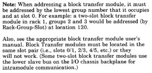
It appears that double-wide modules may be used in 1-slot addressing mode - the pic is from link 2, page 149, under the heading "1-slot addressing"

2012-02-25_234203.jpg
 
Last edited:
1771-IK Help

Have a look at Knowledge Base number 15261 for details on how to set up the addressing for the 1771-IK module using 1 slot addressing. TechConnect is not required.

It basically says to use bits 0-7 of the first slot address for bits 0-7 and bits 0-7 of the second slot address for bits 10-17 for both Input and Output words.
 
If

Have you checked the wiring ?

from link 3 - page 9

"If customer 5V power to the front of the module is lost or the power available signal is not present (or the terminals are not jumpered), bit 17 of the channel word is reset to zero. Since loss of customer power affects all the channels, each channel should show bit 17 at zero after one module scan. This data valid bit, from any of the channels, can be checked in the
program to detect a loss of customer power.

If the data is invalid, bit 17 in each input channel word will be reset to zero. Additionally, if bit 17 is on, and this data is used in a mathematic function, it will inhibit certain mathematical instructions in the PLC controller."

The BTR works, the block transfer enables, goes done, normal stuff. All data is 0, including the valid bit. It does not change when the input voltage changes. It just stays at 0.

I likely do have a voltage out of spec. The voltage required is 15V, 5V, 0V and -15V. The voltage specs are ... off the top of my head ... +/- .2V or .3V. The cards are old and the voltage reference may have wandered a bit. I'm trying to get one of the two-slot cards running to make sure that the addressing is OK.

Is block transfer enabled ?

from link 3 - page 5

"Block transfer programming, not available with all Allen-Bradley PC processors, moves all eight channel words from the module’s memory to a designated area in the data table in a single scan. To use block transfer, the transfer mode switch on the module must be set to block transfer."


It appears that double-wide modules may be used in 1-slot addressing mode - the pic is from link 2, page 149, under the heading "1-slot addressing"

OK - I'm all for avoiding unnecessary work.
 
Ik

Have a look at Knowledge Base number 15261 for details on how to set up the addressing for the 1771-IK module using 1 slot addressing. TechConnect is not required.

It basically says to use bits 0-7 of the first slot address for bits 0-7 and bits 0-7 of the second slot address for bits 10-17 for both Input and Output words.

Thank you - this looks very helpful. It appears that I was turning on the control bits in the wrong control word.

Since I could not access the Knowledge Base without logging in with my TechConnect contract number, I have included the appropriate information below.

Performing single transfer programming to a 1771IK module or a 1771IJ module when in 1 slot or 1/2 slot addressing. This is how the data is formatted when using the 1771IK or 1771IJ module with 1 slot addressing.

When writing to the module:

You Write: To:
Bits 00-07 of the control word--------> Bits 00-07 of 1st module group
Bits 10-17 of the control word--------> Bits 00-07 of 2nd module group

When reading from the module:

You Read: From:
Bits 00-07 of the position word <-------Bits 00-07 of the 1st module group
Bits 10-17 of the position word <-------Bits 00-07 of the 2nd module group
As you said, the information is listed as
Access Level: Everyone

Not sure why I could not access the knowledge base without logging in.
 
Success!

It basically says to use bits 0-7 of the first slot address for bits 0-7 and bits 0-7 of the second slot address for bits 10-17 for both Input and Output words.

Setting bit 7 of slot 7 made the encoder and IK work!

So the 1771-IK works in 1-slot addressing - great news.
 
Working on the IF module

...(or the terminals are not jumpered), bit 17 of the channel word is reset to zero...

Good call. This is one of the problems (if not the only problem)

The jumper from 9 - 10 on the right-hand wiring arm is not conducting. I should probably do point-point checks on ALL of my connections after they are made to make sure that there are no issues with corrosion, poor wire stripping technique, etc.

I guess I may as well jumper the unused analog channels, + signal to signal common, while I'm at it ... tomorrow.
 
Summary

IK - lower 8 bits of first slot and second slot, not all 16 in the first slot.

IF - jumper on 9 - 10 is important


Detailed description for those interested:

The 2-slot module 1771-IK is accessed via bits 0 - 7 in the first slot and bits 0 - 7 in the second slot (which is bits 10 - 17 octal, or 8 - 15 decimal, of the control word and status word)

If set up for single transfer (no block transfer) the msb of the control word must be set to 1.

The lights for A and B channel flicker during movement of the encoder. Marker or O should only show up with you have the encoder in a specific or 'home' location. You can use an external switch for this if you like.

It works fine in single-slot addressing.

The 2-slot module 1771-IF has no control bit issues, since there is no configuration sent to the module. There is a block transfer read from it.

Once the common or 0V, +15V and -15V is properly connected on the left terminal block, the +5V, 0V and the jumper from terminals 9 - 10 on the right terminal block is all connected, the card reads 4 - 20 mA (in my case) and returns the 12 bit values in the block transfer read.

When operating properly, all IF values should read MSB or bit 17 octal or bit 15 decimal as 1. If no connection, under-range will be on as well, bit 14 octal or bit 12 decimal.

It works fine in single-slot rack addressing.
 
Thanks - and end of topic

Thank you Mickey for the links,

daba for trouble-shooting my status description and figuring out that my wiring was wrong,

and Vic for knowing what to search for in Rockwell's Knowledgebase and explaining that I was using the wrong bits to communicate with the IK module.

I appreciate your efforts.:p
 

Similar Topics

Hi All, I am looking at a future project that includes a PLC5 with some digital I/O. Its been a long time since I have worked on the PLC5...
Replies
4
Views
1,588
Hey everyone, Just used the PLC5/Logix migration utility to convert a program, and while addressing the PCEs, I noticed a lot of errors for "XIC...
Replies
12
Views
1,963
Hey everyone, Just a question regarding the conversion of FAL element addressing between a PLC-5 and Logix5000-series processor. In the...
Replies
3
Views
1,615
Can anyone explain to me what this would mean in a COP instruction? Source: #N[N187:4]:[N187:5] Dest: #N[N187:1]:0 Length: 20 I am doing a...
Replies
6
Views
2,205
Ok so to start - im brand spanking new to plc programming. everything i know is either self taught or from the AB manual. im currently...
Replies
17
Views
4,735
Back
Top Bottom