Data Tagging from Micrologix 1400 to Red Lion HMI

calamwill

Member
Join Date
Jan 2016
Location
Manchester
Posts
21
Hi guys, it's the noob again.
So i'm currently in the middle of communicating between a Micrologix 1400 PLC (programmed via rslogix 500) with a Red Lion G304K200 HMI (programmed via Crimson 3), and it was thanks to you guys that i got this far, thank you for that.

But what i want to know now is:
Is it even possible for me to use the data tags from rslogix 500 in the RL HMI to use the buttons on the screen that i have laid out, in Crimson 3? The buttons would equate to B:3/.. bits in the rslogix 500 software and i can't seem to get them to come through no matter what i do.
 
Last edited:
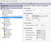
First you'll need to configure your communications to something like this...if over Ethernet.
attachment.php


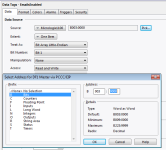
Then select the tag you want to link to the B3, select the source as the PLC you configured above then select your data address.
attachment.php


communications.png tag.png
 
First you'll need to configure your communications to something like this...if over Ethernet.
attachment.php


Then select the tag you want to link to the B3, select the source as the PLC you configured above then select your data address.
attachment.php

is that individually for every tag?

and thank you
 
Create a new flag tag

Source -> your plc (you must have configured the communications already) B003:0000 for B3:0

Extent -> One Item

Treat As -> Bit Array - Little Endian

Bit Number -> 0-15 (0 = b3:0/0 and 15 = b3:0/15)

edit: someone beat me to it with fancy pictures.
 
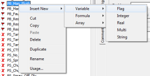
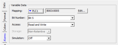
I'm not sure if we're all saying the same thing, but here's some more pretty pictures of the way I do it. First, yes, you need to set up your PLC in the communications page. I call mine PLC1; then in my tags area right click>Insert New>Variable>Flag. Point the mapping to your PLC and then set it up as below.

Screen Shot 2016-01-14 at 8.24.08 am.png Screen Shot 2016-01-14 at 8.24.22 am.png
 
I'm not sure if we're all saying the same thing, but here's some more pretty pictures of the way I do it. First, yes, you need to set up your PLC in the communications page. I call mine PLC1; then in my tags area right click>Insert New>Variable>Flag. Point the mapping to your PLC and then set it up as below.

that way isn't available on mine for some reason.
 
I just realised that my example was from Crimson 2, not Crimson 3...can't see why that would have changed, but no matter. Did you get it working at least?
 
I just realised that my example was from Crimson 2, not Crimson 3...can't see why that would have changed, but no matter. Did you get it working at least?

nope, it's not working yet. i am not sure whether i have done something wrong or not either because i have no idea what i'm doing haha
 

Similar Topics

Hello Everyone, I am using a raC_Opr_NetModbusTCPClient AOI module, as below,. So, I need some assistance to restrict in reducing the poling...
Replies
2
Views
34
Hi everyone, I have a 505 workshop program with PLC type of 555- 1106 and I was wondering how can I download the data documentation window as a...
Replies
5
Views
114
Hello everybody, I'm currently working on a project where I need to implement an IoT platform based on Microsoft Azure Cloud. Communication is...
Replies
2
Views
70
Hello. I have a db which is 1000 INT, and this db is represented in WinCC as a raw data type set of 5x 400 Bytes. This set is read with a script...
Replies
1
Views
79
So i've been at this for a long while, i have Citect Scada 2018, i have full access to everything but i can't seem to find any option or...
Replies
0
Views
67
Back
Top Bottom