SLC Function SLC 5/05 PLC Program

Ones_Zeros

Member
Join Date
Feb 2014
Location
at work
Posts
367
Hello
I'm having an issue with a SLC instruction in a SLC 5/05 PLC program
In the screenshots below I have the "Scaled Source"
The scaled source is a pressure transmitter
then the "rate & offset", I got this from the Allen Bradley Manual
Then I have defined a "Dest"

Ok now if you look at the PID screen shot
the scaling doesnt match the PV. the PV is showing "15"
but the real pv should be around 47

can someone help me please on how to scale this correctly
all the other SCL instructions we have here uses the same scaling parameters and it seems to work this way.


SLC Instruction
SLC.jpg


PID
PID.jpg
 
Last edited:
The PID instruction wants a value of 0-16383 for it's process variable input.
You then use the "Setpoint Max" and the "Setpoint Min" to scale the PV ( process variable) to engineering units. So the way you have the PID set up is if a value of 0 in the PV's input would give a value of 0 for the "Process Variable" in the PID instruction, a value of 16383 in the PV's input would give a value of 100 for the "Process Variable" in the PID instruction. This calculation is done within the PID instruction for you if you use the SMAX and SMIN.

So a value of 2615 as the PV input would be about 15 or 16 for the PV within the PID instruction ( it's doing exaclty what it is suppose to).

2615/16383=.159 *100=15.9

You should set your analog input module (Data format) for "Scaled for PID" which is 0-16383. and use that for your PID PV input. No need for the SCL instruction.

Can you tell us what analog card you are using. Can you post the program (its .RSS file) ?
Zip it first if you can.
 
Last edited:
Thank you for your feedback

The analog card is a 1746-NI4

You should set your analog input module (Data format) for "Scaled for PID" which is 0-16383. and use that for your PID PV input. No need for the SCL instruction.
Not sure in SLC 5/05 how to set this configuration. I couldn't find it

Do i just need to change my setpoint (Max) scaling?


Thanks for the help
 
The reason I ask for the analog card is because some (yours)the data format cannot be changed. Yours (1746-NI4) is fixed depending on the input voltage/current. see pdf

The way you have the "SCL" instruction set up would indicate a 4-20ma input
which is trying to scale the raw data from the analog card to 0-16383.

So yes changing the "Setpoint Max" and "Setpoint Min" to match the pressure transmitter's scaling should work.

How is the pressure transmitter calibrated 0-??? = 4-20ma ? Or? ( WAG, I'm guessing 0-300)
 
Last edited:
Can I ask one more question pertaining to the PID tuning?

now that I have the PID control configured correctly
I was having trouble getting the PID loop tuned.

It seems that this has always been tough foe me to understand.
I have read many articles that explains the mathematical equations on how to tune these loops.

The PID setups I have seen, the "P" & "I" are used but normally the "D" is not used.

In layman terms the way I understand tuning a PID loop is this:

1. always start with the "P" Proportional. This is how far or the amount of change the controlled variable required to drive the loop.

2. the "I" Integral, This is how often it looks for the change, I think its called "sampling" So if I increase this setting the PID would look for a change more often? is this about right.

with my current situation, I have a valve that needs to move based on if the pressure goes higher than the setpoint I have configured in the PID control
The "PV" is the pressure transmitter
when it sees this spike in pressure the valve needs to react rather quickly & start closing.

I was needing some advise on how you tune your PID loops
Can you explain if you don't care?

thanks again!!
 
Post #6 and Post #9 in the following thread might be interesting for a "quick and dirty" starting point ...

http://www.plctalk.net/qanda/showthread.php?p=11761&postcount=6

note that the forum got redesigned several years ago - so the "attachments" are still there - but they've just been moved to the bottom of the posts ...

also - you PROBABLY have the "Trend" feature enabled on your copy of RSLogix500 ... (no offense but) if you're not sure how to set it up to run the graphs, let the forum know and we'll help you get it going ...
 
Last edited:
Ron,
How would I check if I have "Trend" enabled on my copy
Of RsLogix500?

I would like to be able to setup trending
To see the PID graphs


Thanks guys for your help & time!!
 
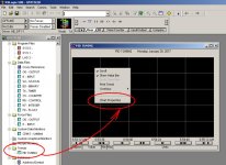
Right-Click on the Trends icon (IF it's shown) ... select "New" from the popup menu - and type in a name ... then Right-Click on the empty part of the graph - and select Chart Properties to start setting it up ...

TIP: the graph will automatically scale itself - but that's very annoying - so use the Custom Scaling option for the Y-Axis values ...

also Double-Click the little "dark-blue" color swatch - and pick something (like yellow) that will show up better on the black background ...

good luck with it ... I'll be offline most of the time - but the other members can give you a hand if you still have questions ...

new_trend.jpg
 
Last edited:
TIP: the graph will automatically scale itself - but that's very annoying

It seems that customer feedback is about as much use as a chocolate teapot....

I have never, ever seen any (finished, aka usable) Trend that has auto Y-scaling - incredibly pointless...
 
Hi,
Sorry to Interrupt in this post.
I am in need of your help.we are trying to do migration for Old PV600 running on Devicenet with SLC 5/05 .We done conversion for the .PVA file in Rsview studio ME edition.We are trying to connect the PVPLUS 700 which we are using after migration on ethernet.On pinging i can see both SLC and PVPLUS 700 on Ethernet.I can do upload/download but my PVPLUS 700 is not communicating with SLC 5/05.Is there any changes required SLC programm to read the HMI.Your help Highly Appreciated.

Thanks

Yogi

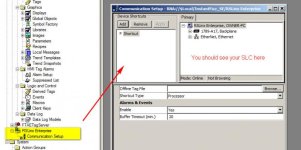
You need to change the communications (RSLinx Enterprise) set-up in the ME application before downloading.

When you do the download, be sure to overwrite the current terminal communications configuration.

2017-01-31_130651.jpg
 
Hey guys
A question on the PID settings I
Encountered today.
I set my "output max" = 40
& the "output min" = 80
I have the "control mode" set to E=PV-SP
but it seems when the PID is in auto mode
It ignores these output ranges.

My goal is since I have a butterfly valve & there is dead space (no change) during the travel from 100% open until about 60% open

I only want the valve to close 40% on high side which equals 60% open

Then I need to close 80% on low side which is 20% open

It ignores these settings on both ranges, what am I doing
Wrong?

thanks again
 
Last edited:
I am not clear on what you are trying to accomplish.

But setting the output max lower then the output min I believe will cause an error. See pdf below.

As far as the limiting not occurring, do you have the "enable output limit" bit set (bit OL)
see pdf.
 

Similar Topics

I'm struggling to implement the test case which is highlighted. What ends up happening is the servo starts when I turn the cycle on, but it...
Replies
3
Views
1,062
I want to average a phorsphorus reading (F8:20) over an hour (4 samples/hr). Ranged 0.03 to 3.0 mg/l. I may want to increase it to 4 or an 8 hr...
Replies
15
Views
5,595
I am building a traffic light simulator that I will be using to demonstrate PLC's at my sons' 5th grade elementary school as part of their STEM...
Replies
1
Views
1,751
Good afternoon. We upgraded to SLC 5/05 processors a few years back but I don't think our MSG function has been working properly. The data...
Replies
1
Views
1,711
Any suggestions on how to increment a counter or other SLC instruction based on a string of integers being not equal to 0. I have determined a...
Replies
6
Views
3,093
Back
Top Bottom