Cascading

PID Loop Updates

Ron:

This is the sort of information that I've been trying to get a deifinitative answer for YEARS. Not the tuning stuff, but some "best practices" in regards to how to tune an AB PID block.

Take this line from the RSLogix5 help file:

Loop Update Time

Enter an update time (greater than or equal to 0.01 seconds) at 1/5 to 1/10 times the natural period of the load (load time constant). Valid range is 1 through 32,767 seconds. The processor divides the entry value by 100 for calculations. The load time constant should be greater than:
1ms(algorithm) + block transfer time (ms)
Periodically enable the PID instruction at a constant interval equal to the update time. For update times of less than 100 msec, use an STI. When update times of greater than 100 msec, use a timer or a real-time sampling.

© 1997 Rockwell Software Inc.

What I think they are saying is that if I set KI to zero, and lower KP until I get an oscillation, the timer preset should be about 1/5 to 1/10 of the peak-to-peak time. Is this correct?

One thing I have done (but abandoned but am considering reviving) is to do a MOV of the timer preset to the PID's Loop Update Time address. Change the frequency in the timer, change the PID, right?

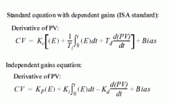
But take a look at the PID equations:

[attachment]

If the dt term is doubled (i.e., if the timer preset term is doubled), then the KI term should be halved, to keep the tuning the same.

Unless you are using ISA, in which case the TI term should double (since KI = 1/TI)

This a simple MOV becomes a oneshot check which PID type and double or half the Integral value. Ditto for derivative (only opposite, since [/i]dt[/i] is in the demonimator).

All this to prevent someone who's inside the PLC from doing harm if he isn't clear on what he's doing and understands what I did.


Independent v. Dependent? Is there an application where one is more appropriate to use over the other, or is it just a matter of how and when you learned to tune / what you are used to?

How about "Derivative on Error" v. "Derivative on PV"?
...for most systems you’ll get better results with this set for PV....
What kind of system WOULD you use "On Error" with?


I notice that Sparky's using an N-type controlled PID, instead of a PD-type, even though he has a 5/40E, which supports PD data files. Would there be any advantage to using PD (other than ease of addressing)?

pid.gif
 
Last edited:
my 2 cents

Where you might use cascade control in this system is on the temperature loop. It would require an additional temperature sensor for inlet air temp. near the point indicated as 'hot air' on your diagram. The outer loop would have the outlet temp. as PV and desired outlet temp. as SP. Its CV would be the SP for the inner loop, which would use inlet temp. for PV. The inner loop CV would adjust the burner.

The typical cascade setup has a fast-acting inner loop (PV responds quickly to CV change) and a slow-acting outer loop (PV responds slowly to CV change). The idea is to not have the burner control valve swing wildly for changes to outlet temp., and possibly toasting the whey instead of just drying it. Rather, the outer loop makes a setpoint change for the inlet temp., which the burner can quickly achieve. This can and should result in the burner valve backing off again before the desired outlet temp is achieved.

Another approach is one that I have used in bakery ovens. Here, we average the hot duct and baking chamber temperatures to provide the PV for a simple PI loop. This has yielded better results than my attempts at cascade control on the same ovens.

As for the pressure (vacuum) control - you say that the damper closes again after the pressure setpoint is reached. Why? Shouldn't it maintain position? (integral action)
 
Re: PID Loop Updates

Allen Nelson said:

Independent v. Dependent? Is there an application where one is more appropriate to use over the other, or is it just a matter of how and when you learned to tune / what you are used to?

Motion controllers use independent gains. Dependent gains would work , but I have never seen them used in a motion controller.
Actually, I just couldn't imagine a motion controller using a reset time in milliseconds.


How about "Derivative on Error" v. "Derivative on PV"?

What kind of system WOULD you use "On Error" with?

Motion controllers use the error for all three PID terms.

One should use the SP-PV when the SP is ramped smoothly from value to the next like a motion controller would when moving from one position to another. One should use PV for the derivative and proportional terms when the SP can make step jumps.
Can you see why? If you know why you will always know which to use.
 
Yo, Peter N,

Again, I take no offense at what you said about “slowing down the PID” - but I’m really trying to find out what I said that you interpreted that way. I went back over my previous posts. Is this it?

Let’s just suppose that you (incorrectly) execute the PID every single time that the rung gets scanned. That’s really too often.

If that’s what you’re talking about - then I still respectfully stand by what I said - but please let me elaborate.

Many beginners try to put their PID instruction on an unconditional rung. In many situations that results in the PID executing its math equation each and every time that the rung gets scanned. Now - that’s pretty darned fast. Not that there’s anything wrong with “fast” - except that, when controlling a system with a slower response, going “fast” just unduly burdens the processor with mathematical “busy” work. Still, if “the PID is hogging the scan time” isn’t an issue (and it rarely is) - AND if the “loop update time” and the actual PID “execution time” COULD be synchronized - then this “unconditional rung” strategy would work OK. But a problem arises when we start to consider the actual time which elapses between successive executions. If the rung is unconditional, then the time between successive PID executions is solely dependent upon the scan time. And that amount of time CAN fluctuate from scan to scan - depending on true/false logic, etc., etc.

Now in practice, diehard technicians CAN get the PID to work with this “unconditional rung” setup. If they tinker around long enough with the tuning parameters - and also with the loop update time - they can eventually (well, usually) get the loop tuned for adequate control - even though the PID is being executed at an extremely fast rate. But sooner or later - something causes the scan time to increase significantly. Usually this is caused by additional ladder rungs, more subroutines, etc. being added to the program. That increases the processor’s scan time and - as you well know - causes the loop to lose its tuning. Which is what I was getting at when I said:

Plus - even worse - the elapsed time between successive scans might vary considerably from scan to scan.

Faced with this situation, the technician usually grumbles something along the lines of “piece of junk won’t stay tuned” and goes back to tinkering with the settings.

As many of you know (from my user profile) I work as an “inside technical support” person for an Allen-Bradley distributor. One of my job duties is fielding customer phone calls for technical support. Whenever you see lengthy posts like this it usually indicates that “all is well” out there in the field - and I’ve got time to type between calls. Anyway -

Whenever I have a customer call in about a PID problem, the very first two things that I ask about are: (1) the “loop update time” setting - and (2) the conditions being used to “trigger” the PID’s execution. In the VAST majority of cases, these two conditions are not set up correctly. Once the customer has these two items properly set up, then they have a fighting chance of being able to tune the loop. Conversely, if these two conditions are NOT set up properly, then the chances of finding a satisfactory solution to the customer’s PID problem are very slim indeed.
Look at a typical complaint from the customer’s point of view. Let’s say that we have a machine with PID control which has been adequately tuned and running along fine for several months - with absolutely no problems. Now, all of a sudden, the machine is “out of tune” and we’re wasting product. We haven’t touched the tuning values - or altered the control for the machine in any way. And the machine itself hasn’t been changed either. So what’s suddenly causing the problem?

How about that ladder logic program addition for a new (totally unrelated) piece of equipment? A large number of new rungs were added - and most of them contain extensive math operations - and other features which are “scan time” intensive. So the processor’s scan time has been increased. But that won’t affect the PID will it? If the PID were set up right it wouldn’t - but this customer just happens to be operating his PID on an unconditional rung. The tuning values he’s been using were based on the elapsed time between successive scans of the PID. But - and here’s the trick - now (due to the large program addition) that elapsed time between successive scans has increased - so the old tuning values aren’t quite right anymore. Specifically, the Integral action and the Derivative action (which both take the execution time into mathematical consideration) are now skewed from their original effects on the controller’s final output. And so the plant’s production is suffering. So the technician grumbles something along the lines of “piece of junk won’t stay tuned” and goes back to tinkering with the settings.

One point I’d like to make is: As soon as ANY type of “tuning” issue arises, the first thing we invariably hear is “should I increase the integral ...” or “should I decrease the derivative” and so on - and so on.

Sometimes it’s like trying to help someone troubleshoot “I can’t get the car to start” over the phone.

“The car won’t start so we replaced the spark plugs. We replaced the ignition coil. We shaved the cats. We girdled the oak. We took the wheels out and put butter in. Nothing helps. So what do we try next?”

“How about the gas? Are you sure that you have gas in the tank?”

“Hold on - let me check. OK, thanks, we got it working now.”

And - yes - it usually ends up that adjustments to the integral - or to the derivative - really are necessary. BUT! - if the “loop update time” and the PID’s execution “trigger” aren’t matched up FIRST, then the necessary adjustments to the tuning parameters are EXTREMELY difficult (if not impossible) to make. On the other hand, once the “loop update time” and the PID’s execution “trigger” ARE correctly matched, then a lot of other problems seem to become much more manageable.

Specific case in point: We had a customer recently with four identical pieces of production equipment - each one was controlled by a separate PID - all in the same PLC program. The customer was annoyed (to put it mildly) that there was absolutely no consistency for the tuning values from one system to the next. I mean they weren’t even close. The settings for Kc, Ti, and Td were all over the board. The plant technicians wanted them all to be set the same from one machine to the next - or at least close to the same - to make it easier to troubleshoot.

You know what’s coming next. We took a look at the “trigger” timer Preset settings. Three of them were at 100 (correct for this application) - but one of them had been incorrectly set at 1 - so it was, in effect, executing 100 times “faster” than its brothers. Next we looked at the “loop update times” for each PID. These were all up, down, and in the middle - and (if memory serves) I don’t think that any one of them matched the “trigger” time interval. So we recommended that the customer first correct these settings - and then retune the systems. As it turned out, they only needed to retune one of them. Once they came up with a set of “good” turning settings, they plugged these into the other three PID’s as a “starting point” for tuning - and everything else just sort of fell into place.

And so, Peter, there IS a point which I have been trying to make - and apparently from your posts in a couple of threads - I’m failing miserably in making myself understood. Now I KNOW that you understand these issues - undoubtedly far better than I do - but still it looks (based on how I read your posts) that you’re interpreting my observations on the “loop update time” and the PID’s execution “trigger” as either trivial (which I doubt, because you of all people would know that they are far from trivial) - or else I’m not making myself very clear on the thoughts which I am trying to convey (very likely - although I’m trying really hard).

Anyway, those are the basic “timing issue” ideas that I meant to convey. I apologize if I didn’t make myself clear. I certainly didn’t mean to imply that a “slowed down” PID would give BETTER control than a “fast” one. Personally, I’ve never seen that happen. Of course in this sense, I’m using the terms “slow” and “fast” in referring to the elapsed time between successive executions of the PID.

And in that same sense, I HAVE seen situations where a PID - which was being executed on a “fast” schedule - could be “slowed down” to a more conservative schedule. Granted, the control never got any BETTER - but it didn’t get any worse either.

Note to SLC people: In the SLC platform, you MUST (thank you, Allen) put your PID on an unconditional rung. You may then select the “Timed Mode = TIMED” setting. The PID will then automatically be scheduled at whatever time you have entered for the “Loop Update” setting. Notice that in this thread we’re not working with an SLC. This thread is concerned with the PLC-5 platform and the PID is somewhat different with these larger processors.

Now a note to Tom Jenkins: If I understand you correctly, then part of your personal PID tuning strategy is to increase and decrease the “loop update time” setting - without changing the operation of the external condition which is used to “trigger” the PID into execution. (Usually this is a timer done bit.) I think this is one of the senses in which you are using the terms “speed up” and “slow down” the PID. I have no intention of trying to argue with your success. That having been said, I know that you will fully understand what I’m about to say in my next post. (I ran out of room in this one.)
 
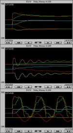
The purpose of this post is to further flog a dead horse - I feel as though I’ve beaten this “loop update time” issue to a pulp. Anyway, maybe a picture will help. Shown below is the output of a test rig in my lab which simulates an air flow system. Not only does it show the customary Setpoint, Process Variable, Control Variable traces, but it also breaks the Control Variable down into its component parts.

[attachment]

BLUE = the Process Variable or air flowing through the system.

WHITE = the Setpoint. In each graph, this goes from 819 (20%) to 1638 (40%) in one step as the test begins.

RED = the Proportional component of the PID’s output.

GREEN = the Integral component of the PID’s output.

YELLOW = the Derivative component of the PID’s output.

ORANGE = the Control Variable or PID output - which mathematically is the algebraic sum of all of the three individual components. In the actual test system, the output is used to position a butterfly damper valve mounted in the air stream.

I’m sorry if some of the colors became muddy in saving to a JPG format. Just do the best you can.

The graphs are scaled so that the top of each graph is 5000 counts. The bottom of each graph is (note negative sign) -2000 counts. The X-axis of each graph is 66 seconds. In all of the graphs, the tuning parameters remain set at Kc=1.40; Ti=0.14; Td=0.03. The PID execution “trigger” event is a timer done bit. In all of the graphs, the timer preset remains at 50 (for a one-half second period). In each graph, the process is allowed to stabilize at a setpoint of 20% flow. Then the “loop update time” setting is altered to obtain the test value which is shown at the upper corner of each graph. Once the “loop update time” has been set for the test, the Setpoint is then increased in one step to a new setting of 40%.

In the top figure, the “loop update time” is set for 0.50 seconds - which (correctly) matches the PID’s execution “trigger” event - a timer done bit which fires at a period of 0.50 seconds.

The results of the test shown in the top figure demonstrate what we will consider to be an “adequately tuned” response.

In the middle figure, the “loop update time” has been DECREASED to a setting of 0.05 seconds - which is (incorrectly) set for one-tenth of the period of the PID’s execution “trigger” event - a timer done bit which remains set to fire at a period of 0.50 seconds.

In the bottom figure, the “loop update time” has been INCREASED to a setting of 5.00 seconds - which is (incorrectly) set for ten times the period of the PID’s execution “trigger” event - a timer done bit which remains set to fire at a period of 0.50 seconds.

Well, folks, based on what I see before me, I’d say that messing around with that “loop update time” setting can make some weird things happen to your system’s response. To be sure, we are making some significantly large alterations to the “loop update time” in these tests - but the fact remains - this is what I’d call a ... shall we say “flamboyant” ... way to tune a control loop.

Whenever we DECREASE the “loop update time” setting - without changing the operation of the PID’s “trigger” - then the net effect is to alter the operation of the PID in the following ways: We get no change to the amount of Proportional action. We get LESS Integral action. We get MORE Derivative action. Now at first glance it would seem that these changes (one stays the same; one goes down; one goes up) would result in a net effect of no change to our PID’s output. But that’s not what actually happens. The derivative action functions (in simplest terms) like a “brake” on the PID’s output. With the idea of “increasing the braking action” in mind, we can see that whenever we decrease the “loop update time” setting - without changing the operation of the PID’s “trigger” - then (in simplest terms) the net effect is to DECREASE the output of the PID.

Whenever we INCREASE the “loop update time” setting - without changing the operation of the PID’s “trigger” - then the net effect is to alter the operation of the PID in the following ways: We get no change to the amount of Proportional action. We get MORE Integral action. We get LESS Derivative action. Once again, at first glance it would seem that these changes (one stays the same; one goes up; one goes down) would result in a net effect of no change to our PID’s output. But that’s not what actually happens. Remember that the derivative action functions (again, in simplest terms) like a “brake” on the PID’s output. With the idea of “decreasing the braking action” in mind, we can see that whenever we increase the “loop update time” setting - without changing the operation of the PID’s “trigger” - then (in simplest terms) the net effect is to INCREASE the output of the PID.

So that’s the big picture in a nutshell. Now let’s look just a little bit deeper. Not only does increasing the “loop update time” tend to increase the overall output of the PID - more importantly, it skews the relationship between the different components of the output. Specifically, the ratio of the Proportional action - to the Integral action - to the Derivative action - all of these interrelated ratios are altered. So while we might wish to just sum up by simply saying that we’ve “increased the PID’s output” - there’s more to it than that. Not only have we increased the output - we’ve also fundamentally altered its shape. And that’s going to have an effect on the response of the Process Variable that we’re trying to control. Will we get better control - or will the control be worse? We can’t say for sure without actually experimenting on whatever particular system we’re trying to control. But the main point (and yes, I do have one) is that:

The relationship between the “Loop Update Time” setting - and the “Trigger” event which is used to schedule the execution of the PID instruction, is important. Most “knowledgeable” technicians say that the two values should match. If the values don’t match, then the operation of the PID might be significantly less than optimum. Further - tuning the PID might be made much more difficult - if not impossible.

In practice, some technicians use this effect quite successfully in their loop tuning careers. I’d say that Tom Jenkins seems to fall into that category. But others still maintain that the “proper” way to achieve the same effects on the PID output is to get the “loop update time” setting correct and then leave it alone - and to then “tune the loop” by altering the individual settings for the Proportional, Integral, and Derivative actions. Who’s right? Who’s wrong? Personally, I never argue with success - but I don’t mind telling you, this particular approach is just a little too weird for me.

One more note: In my humble opinion, most people who gripe about things like the Ziegler-Nichols method, etc. - haven’t given the system a fair chance - not unless the “loop update time” issue has been taken care of first. And in many (most?) cases it has not.

My work here is done.

lut.jpg
 
Ron, sorry about that.

Ron, I jumped on Tom's post 11 paragrah 2. By reading all your posts, I see your are more concerned with setting the PID update period parameter with the actual PID update period. This is a valid concern on the PLC5.

I have had people ask me to slow to the loop ( slow down the update time) on motion applications. This drives me nuts because as you pointed out, it is not the right way to tune a PID. I didn't want to have a bad idea propagated as 2000+ people read these posts now. In addition, it is a misguided attempt to compensate for dead time. Sometimes the customer has a hard time understanding how the integral and differential gains must be scaled by the update time before use in the PID. Please refer to reducing the response as reducing the response or reducing the gains. This will avoid confusion and misleading people

PID updates should be done much faster than the natural frequency or time constant of the system. ( Time Constant = 1 / natural frequency in radians/second ). Anything over 100 PID updates per time period may be excessive depending on the application. Anything less than 10 will make tuning difficult and hinder performance.
 
Another whack at that there dead horse:

I agree, Ron that trigger and update times should be the same - the mechanics for doing so are a function of the PLC platfrom executing the loop. I usually "roll my own" algorithm, which is an amalgam of various techniques, and the trigger and update are inherently in synchronization as you reccommend.

I deal primarily in processes with a large dead time, and have never been involved in motion control. I suspect the response times are orders of magnitude different, and the tuning is therefore different as well. Sparky's temperature loop is inherrently going to be a slow response system, and if he takes the approach of reducing the intervals the loop is solved per our reccomendation it should help him. I don't think we have substantive differences in our approach.

I do have to get in one last whack of the concept of PID being the only approach to an analog control problem. The algorithm is obviously time tested and works quite well for a large class of control problems. But it isn't the only approach to be investigated. Back when pneumatic controls were the only game in town PID was a giant leap forward. The algorithm was adapted to electronic controllers, and then digital control, and PLCs for good reason. But if you truly understand the process you are controlling, you have to make a decision as to the control logic that will provide the best result for the operator on the line. Sometimes that's PID and sometimes it isn't.

The tendency I dislike is for engineers and programmers to automatically assume PID is the only viable technique. That decision has to account for the operators using the system as well as the control result. If they can't tune the system, the control logic should be reviewed to make sure the algorthm selected is appropriate for the entire system, and the entire system includes the operators.
 
A Whole lot of thanks!!!!

To every one who posted replies, a huge thanks. I realized and learned more about the true nature of PIDs and how they function in this forum during the past few days than I have in the last two years of programming PLCs. I had to get my hands dirty and find allot of information about how the process works and how fast it works. Just the relation of how the total process works has helped but you guys have given me the information to know what to do with those numbers.
I am happy to say that the PID is tuned to "acceptable" limits. I know it is not to its optimum, which will come next. The PID keeps the chamber vacuum within .20 inH2O> I don't know about the physics of it but to me a chamber that size, maintained that precise of a vacuum, is pretty good.
Once again a big thanks to every one!!!!!

It has been an excellent example of my Quote
beerchug
 
What the trend looks like

I just thought I might post a bit map of the trend for every one to see. The green is the chamber pressure *100. The orange is the gas valve CV. Yellow is Gas valve set point. Red is the gas valve PV. and white is the pressure PV.
 

Similar Topics

Good Evening , I have a Conveyor system that requires Speed Cascading from one conveyor to another. Meaning that if one conveyor speed is...
Replies
10
Views
2,587
Happy Holidays Folks! I am working on a robot cell and as we are adding PLC control to the system, I have some questions about implementing an...
Replies
6
Views
4,734
I'm new to PLC. Have little knowledge of VFDs. I've 5 nos of Delta M series VFDs and all are connected to motors running the conveyor belts...
Replies
3
Views
2,850
Hello. I am a student doing an independent study on PLCs. I am using a Allen Bradley SLC 5/02. What I am trying to accomplish is to step a simple...
Replies
7
Views
4,227
I am wondering if its a good idea to cascade pid loops. For example If I want to control two variables Current and Voltage. If i can feed output...
Replies
4
Views
2,768
Back
Top Bottom