Modbus RTU

The master does wait for reply from each node according to a set timer. In the meantime it tries to request from other nodes.

I’m not sure about silence time, since I’ve never heard of it before.
Do you think issues like that can occur when the master is not from same vendor as the slaves?
In theory the mixing of vendor products should not matter since they should all comply to the standard.

As an example of where not following the silence period can cause a lack of response, consider that a request is sent, then your software hesitates to calculate the checksum. The checksum is then sent, but there was a 2 character time delay. The receiving device may discard the part of the packet without the checksum since it saw more than a 1.5 character silence and not receive it all as a single packet.

Now consider the other possibility. Your software sends a packet to one device, but does not wait 3.5 characters before sending data to the second device. The first device may concatenate both of the packets into a single packet therefore not seeing it as valid.

In short, be sure your software is putting all data of a packet on the wire without hesitation. Also be sure to wait long enough before transmitting the next packet.
 
The master does wait for reply from each node according to a set timer. In the meantime it tries to request from other nodes.

This didn't sound right to me. Does this mean that while waiting for a node to respond that you are trying other nodes? If so, that could cause a data collision.

Jerry
 
This didn't sound right to me. Does this mean that while waiting for a node to respond that you are trying other nodes? If so, that could cause a data collision.

Jerry

It's pretty normal to have a timeout timer and move on to the next node. If a node doesn't respond within a few seconds, it is probably not going to.
 
It's pretty normal to have a timeout timer and move on to the next node. If a node doesn't respond within a few seconds, it is probably not going to.

OP writed that polling rate have increment to 100ms. Polling rate should be more than timeout for slave.
If next query is sended before earlier slave have responded for eralier query or before query timeout, it will make collisiona on bus and communications don't work right.
 
ModbusRTU makes use of silence periods to determine end of packets and also used to clear receive buffers. Some devices adhere very strictly to this and may ignore a packet because it cleared the buffer prematurely from the silence.

Does you system honor the 3.5 and 1.5 character of silence rules?

I have checked the data sheet for the slaves, and have verified that the slave has a 3.5 character silence period.

Manual for slave says the following:


The end of frame is recognized when no transmission takes place during the time period required for the transmission of three and a half characters (3.5 times character delay time) (see Modbus Protocol Reference Guide).


Does this mean that the master also has to have a setting with the same 3.5 silence period?

Thanks!
 
Does this mean that the master also has to have a setting with the same 3.5 silence period?
Yes. If you are using an RS485 network, all slaves hear the same data. If the master were to put a packet on the wire targeting node 1, then immediately put a packet put another packet on the wire targeting node 2 without 3.5 characters of silence, all nodes would hear this as a single concatenated invalid packet.
 
For me Modbus RTU lacks a "bytes to follow" field in the packet header as Modbus TCP has, this would make the 3.5 silence unnecessary
 
For me Modbus RTU lacks a "bytes to follow" field in the packet header as Modbus TCP has, this would make the 3.5 silence unnecessary

True

As a master, the master controls the flow. Issue a request and the master can calculate the number of bytes to be returned. The count will be the response expected or the error response count, for RTU, IIRC, 9 bytes.

A slave can guesstimate the number of bytes after a few bytes have arrived. Error checking still has to be done before actions to reply. The end of the message can be determined before the "silent" time elapses.

I did find it interesting, without knowing more about the slaves, speed, any slaves powered off, etc., that 100ms was allowed for a slave to respond before issuing the next message (other than after a broadcast). For some low horsepower slaves, especially slaves that are using I/O pins for 485 control, (not using a dedicated IC) 100ms is...not advised.

The master logging all request/response could help to zero in on a problem slave. A simple test to run is set the response allowed time to 2 seconds before the next request is sent. Run the test for X time, more than the normal failure time and if the problem vanishes, it indicates the master needs to increase from the 100ms.

Another issue can be slaves releasing the wire, entering the tri-state mode after transmitting. The master, assuming is it much faster, receives a response, handles it and issues the next message. The slave that sent the last response, has not had enough time to release the bus and is still trying to drive the bus while the master is trying to send the next message and drive the bus.

My2c.
 
I did find it interesting, without knowing more about the slaves, speed, any slaves powered off, etc., that 100ms was allowed for a slave to respond before issuing the next message (other than after a broadcast). For some low horsepower slaves, especially slaves that are using I/O pins for 485 control, (not using a dedicated IC) 100ms is...not advised
My experience as well.
A simple test to run is set the response allowed time to 2 seconds before the next request is sent. Run the test for X time, more than the normal failure time and if the problem vanishes, it indicates the master needs to increase from the 100ms.
I concur.
 
3: The closes node with issues is only approximately 60 feet away, so I don’t see the need for a repeater.
The issue is not the need for repeater action, as much as it is for isolation from a ground loop that can vary over time and also for biasing. Some isolators have biasing built-in.

There's an app note here, that describes a voltmeter check for additional biasing:
https://www.icpdas-usa.com/documentation/DC Bias Tech Note.pdf

The company ICP-DAS makes a module with screw terminals that applies either termination and/or bias. Note that for bias, you need to dig in and find the V+ and GND on the 485 chip and bring it out to the module, but that's true no matter which devices are used.

The module spec sheet is
https://files.icpdas-europe.com/products/K126689/web/icpdas/datasheet-tm-sg4_cr.pdf

The Bias is applied at one point in a 485 multidrop network:

Bias_at_one_point_in_the_485_multidrop_network.jpg


The DIP switch settings for Bias
ICP-_DAS_t_M-_SG4_module_wiring_and_DIP_switches_for_Bias.jpg
wiring is shown here:
 
I'd also like to mention that there are a few tools needed to troubleshoot RS485 buses.

1. RS485 transceiver for PC connection
2. Software that can record communication
3. DSO or analog scope

Basically you need to have the ability to sniff the communication on the bus. So you can check what was sent and when.

Secondly you need to be able to look at the signals to determine if there are electrical problems. A bias resistor problem for instance would be obvious looking at it with a scope.

Finally, the modbus master must be able implemented correctly so it can re-transmit when there are communication errors. That is why modbus have a checksum and are sending acknowledge messages.
 
Oh, this is a classic problem.

With 98.4% certainty your problem is that you haven't installed any bias resistors.

In a point to point configuration 4 wire configuration the transmitter on both the master and the slave are driving the bus into a known state.

In a multidrop configuration nobody is driving the bus between requests and replies. The RS422/RS485 drivers are in tri-state mode. That means the bus is in an unknown state. That makes it extremely sensitive to interference so you will get lots of ones and zeros which will trick the receivers into looking for messages which don't exist and miss the ones that do exist.

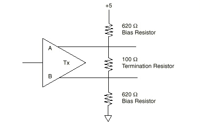
Bias resistors will put the A/B side into a known state. One resistor will pull up one wire to +5V and the other will pull it down to 0V. With the standard termination resistor in the middle.

bias.gif

Image from http://www.ni.com/support/serial/resinfo.htm

Quality RS485 converters have these bias resistors already installed for multidrop so you don't have to put them externally.
Actually, your company should have had them as well on your modbus. It's a hardware design mistake to not include them on a multidrop configuration.

Thanks a lot for this post.
We put in a 485/485 galvanic isolator that had the bias resistors internally.
After installing it in the network, the communication started to work perfectly.
Had to adjust the polling time, but after that we have had no problems.

Do any of you know of any webpages where I can find good info on polling time, message delays etc..
 
Do any of you know of any webpages where I can find good info on polling time, message delays etc..
I have NEVER seen a manufacturer publish a spec for response time to a poll. The response time of a slave is what it is.

Part of the issue (in publishing a spec) might be defining what constitutes a 'Modbus task'. Accepting an FC16 write of 50 registers might well take longer to execute than an FC03 read of 2 registers. Another is dealing with devices that can experience different 'loading' which would affect execution and response. And if a spec is published, there's an expectation. No spec, no expectation. It is what it is.
 

Similar Topics

Hi, I'm having an issue with a mircologix not transmitting out. The current setup is a mircologix 1400 connected to a Guardian 100 Radio...
Replies
1
Views
105
If a device has Modbus RTU over serial and Modbus RTO over TCP and Modbus TCP then there is a difference between Modbus RTU over TCP vs Modbus TCP...
Replies
7
Views
443
Kindly, I am trying to do some Modbus Rtu communication between a 1214C Siemens plc and the following slaves. ( Schneider PM5110 meter , Socomec...
Replies
4
Views
243
Anyone have some info for how to control a TECO EQ7 series VFD via Modbus RTU? We originally installed a pair of Yaskawa GA800s at the remote...
Replies
3
Views
334
Hi Guys, I am a new member and this is my first post! I have a little PLC experience but it is mostly with siemens logo and using ladder...
Replies
4
Views
891
Back
Top Bottom