How does wrt.not work in fanuc plc programming?

alive15

Member
Join Date
Oct 2015
Location
Montgomery, AL
Posts
690
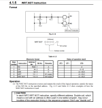
Good afternoon all, hope everyone is doing well. Could someone explain the pic attached on the wrt.not instruction? To me, it looks the same as the regular wrt instruction. I really don't understand it's purpose at the moment, and looking to get some clarification on how it works?

I thought it would prevent the output from coming on, but looking at the status of operation result on the right side confuses me, as it gives the same status as the regular wrt instruction.

Thanks!
wrt.not.PNG
 
Right, so if all input conditions are met, I would think y11.1 would be = 1, and y14.6 = 0.

So I don't get the purpose of setting the output = 0, because I could just add more input conditions to prevent it from happening?
-----
Ahh, actually now I get it, the output would be on if the input condition is false, and it's off if all input conditions are true.

Has anyone ever used that logic for any particular application? To me, it feels like the wrt.not makes the output a normally closed signal, but wouldn't it be easier to have normally open output and just change inputs to be n.o or n.c.?

It's very interesting now that I understand it, but I don't see any particular scenario where wrt.not would be preferred over wrt. It's almost like a preference choice, not an engineering / design choice?


Yes, it's just a negated output, and it's not necessary, but available if you want it.
 
I once found a practical use for the negated coil instruction.

Back before the GE Fanuc 90-30 added an off delay timer to the instruction set I could create one using a standard timer with a one-shot triggering the timer block and a negated coil as the output of the timer. Firing the one-shot turned the negated coil on and it stayed on until the timer timed out.

Then they added the off delay timer at a later firmware version....
 

Similar Topics

I am trying to connect with a Schneider plc which has a firmware version only available in Somachine v4.2. In Machine expert After taking upload...
Replies
0
Views
110
They are installed in a control panel that was made in France and are intended for the termination of analog inputs. Each of the red capped...
Replies
4
Views
412
So, I'm really just trying to get some experience by practicing with arrays. I'm using studio 5000 v33. I have one rung with an XIC bit that's...
Replies
5
Views
229
I tried researching but I still don't quite get it. As far as I understood, it's used after a function is called in STL and then if the function...
Replies
1
Views
143
Back
Top Bottom