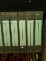
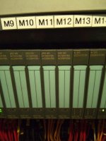
Siemens ET200S

You need to come up with much more information.
Type no of ALL modules.
What is the ET200S rack connected to and how ? (Profibus or Profinet)
Status of ALL light indicators (take a photo).
Is this a new setup, or is it an existing setup that used to work ok before ?
etc...
 
I had a problem with some Siemens stuff (like this one . . exact model not sure.)
My stuff communicates over Profibus. The machine would not run. . . . One of those I/O boxes had a red light on it . . . I powercycled the machine and when things came back up the light was green and everything worked again.

Is there an easy way (From the PLC or the Step 7 project) to check the health of the Profibus itself?
Mad Poet.
 
Open the hardware configuration.
Go to File.
Open ONLINE.

In there you can click on the stuff you have defined and the information will be real time such as faults that the cards in the Station may have.

If you activated diagnostic for open circuit or short circuit, that would be displayed there.
 
Also make sure you have the correct OB's in your program to do error handling.
 
I am still working on ET200s PLC
The PLC (ET200S) cannot receive any command when i turn the output on from the my laptop and non of the output card is working. the CPU is IM151-7 what could be the problem

is it that the cards are bad
 
I am still working on the ET200S the PLC after uploading the program to my laptop, i try to force any of the output put it is not receiving any command. That is, i can't modify to 1 when I try to issue the command. even when i write i a simple program and download modify to 1 was successful but the output card still didn't work

is it that the output card are bad
and for the program that refused to modify to 1 is it that the program is protected?? because there was no message if so what will i do?
 
Mind you, I don't know enough to actually help you here. But, I would start by checking all the indicator lights - are any of them red as in is something faulted?

Cardosocea mentioned 'stuff you have defined' . . . Is the ET200S defined inside the Step 7 program?

I also get the impression you don't really understand what you have here? From what I see, the ET200S is an input output rack. There must be an actual PLC somewhere . . . You also mentioned an IM151-7 . . . Which appears to be :
>>> IM 151-7 CPU Interface Module >>>

>>
Reading and writing the I&M data of the IM 151-7 CPU with STEP 7
Reading:
● In STEP 7 the I&M data are displayed under "Module state – IM 151-7 CPU" ("General"
and "Identification" tabs) and via "Available nodes" (Detail view) (see Online Help for
STEP 7 ).
● In the user program, the I&M data can be read via SFC 51. Specify the required SSL
sublist number and the index in the input parameters of the SFC 51 (see table below).
Writing:
You will always need STEP 7 HW Config to write the M data of modules.
For example, you can enter the following data during configuration:
● Name of the automation system (device name)
The device name is assigned when you create the station in SIMATIC Manager. In this
case a "SIMATIC 300(1)" station is created by default. This name can be changed at any
time.
● You can enter the following data in STEP 7 HW Config on the "General" tab under "CPU
Properties":
– Name of the module
>>

https://cache.industry.siemens.com/.../v1/im151_7_cpu_product_information_en-US.pdf

This is a link to some information I found on the IM151-7 module . . .

What is the CPU? how does the CPU communicate with these I/O modules?
MadPoet.
 
reply

Mind you, I don't know enough to actually help you here. But, I would start by checking all the indicator lights - are any of them red as in is something faulted?

Cardosocea mentioned 'stuff you have defined' . . . Is the ET200S defined inside the Step 7 program?

I also get the impression you don't really understand what you have here? From what I see, the ET200S is an input output rack. There must be an actual PLC somewhere . . . You also mentioned an IM151-7 . . . Which appears to be :
>>> IM 151-7 CPU Interface Module >>>

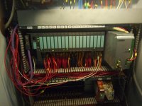
>>I Uploaded the program to my laptop so all configuration was uploaded two see attached
Reading and writing the I&M data of the IM 151-7 CPU with STEP 7
Reading:
● In STEP 7 the I&M data are displayed under "Module state – IM 151-7 CPU" ("General"
and "Identification" tabs) and via "Available nodes" (Detail view) (see Online Help for
STEP 7 ).
● In the user program, the I&M data can be read via SFC 51. Specify the required SSL
sublist number and the index in the input parameters of the SFC 51 (see table below).
Writing:
You will always need STEP 7 HW Config to write the M data of modules.
For example, you can enter the following data during configuration:
● Name of the automation system (device name)
The device name is assigned when you create the station in SIMATIC Manager. In this
case a "SIMATIC 300(1)" station is created by default. This name can be changed at any
time.
● You can enter the following data in STEP 7 HW Config on the "General" tab under "CPU
Properties":
– Name of the module
>>

https://cache.industry.siemens.com/.../v1/im151_7_cpu_product_information_en-US.pdf

This is a link to some information I found on the IM151-7 module . . .

What is the CPU? how does the CPU communicate with these I/O modules?
MadPoet.
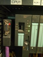
The PLC is not connected to any other PLC it is working as a stand alone

IMG_20170320_125747.jpg IMG_20170320_125824.jpg IMG_20170320_130458.jpg IMG_20170320_133446.jpg
 
This IM-151-7 has a CPU in it. It can be used as a dumb IO module or as a PLC (which could possibly take over some function in case of comm fault).

Where is that Profibus cable going to? Is it going to another PLC? Or another IO rack?

Do you have the original project and the correct TIA Portal version?

How are you turning on the output?? Are you modifying the program? Are you forcing on the hardware configuration?

Did you manage to read the diagnostic information on the CPU?

The cable is going to an HMI the program is step7 v5.5 i uploaded the program from the PLC, and try to force an output but no response even the program could not be modified and also, the output that is high refused on the program couldn't power the output module

my challenge is:
1) I could not modify to 1 or force an output when am online with the program uploaded

2) non of the output module LED is showing green

3) could it be that the output cad are bad
 

Similar Topics

I was trying to communicate between Siemens ET200S IM-151-8 PN/DP CPU to Rockwell Allen Bradley L73 through Hilscher Gateway NT100-RE-EN. Using...
Replies
0
Views
105
Hi there, I'm having major issues in connecting a Siemens S7-300 315 with an ET200S through Profibus. I've tried many methods but I'm really...
Replies
11
Views
2,798
I'm configuring a profinet network in TIA portal v13, comprising the following components: S71500/ET200MP processor TP1200 HMI 2 x IM 155-6 PN...
Replies
3
Views
2,258
Hi all, I have successfully connected my new wirelessHART sensors to the master station, but am struggling to find a comprehensive guide on how...
Replies
1
Views
1,701
Hi all, Hardware: siemens S400 /profibus dp/ ET200s/ IM 151-1 Software: PC using Step7 v5.4 sp2 I'm trying to add more hardware onto an...
Replies
14
Views
6,128
Back
Top Bottom