micrologix 1200 relay output?

matlark

Member
Join Date
Jul 2011
Location
KY
Posts
102
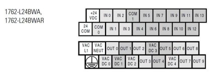
Does this mean it can run 24vdc and 120vac relays depending on which of the 10 outputs are used? Whats the difference from OUT 0-9 and VAC DC 0-4?

thanks
 
Generally MicroLogix outputs are grouped together; there will be a group with a common source power terminal for the high-speed DC outputs, then another group with a common source power terminal for the standard DC outputs, then a couple of groups of relays.

The only way to be certain about how these are hooked up is to look at the connection diagram in the MicroLogix user manual for your specific controller.

MicroLogix termination confuses me, with the grouping and the staggered terminals. I always print out the connection diagram and keep it with me when I'm wiring a MicroLogix so I can double-check my schematic or hookup diagram against the actual controller.


The "VAC DC" label generally means it's the common source terminal for a dry relay contact.

Yes, you can run different voltages on adjacent but separate relays or relay groups.

I don't like to do it, but if I'm careful with my wiring (I almost always use ferrules if I'm mixing voltages) I will.

What is the exact hardware part number of the MicroLogix you are using ?
 
Okay, that model has only relays, and no DC solid-state outputs.

The relay "commons" are grouped together, both to fit the terminal count of the MicroLogix frame and to provide the mix of voltages or functions that most users will need.

Terminal "VAC DC0" feeds Output 0
Terminal "VAC DC1" feeds Output 1
Terminal "VAC DC2" feeds Outputs 2 and 3
Terminal "VAC DC3" feeds Outputs 4 and 5
Terminal "VAC DC4" feeds Outputs 6, 7, 8, and 9

The relays inside are identical, so the ampere capacity of all outputs are the same. The limit of 8A per output Group applies, as well as the ampere limit per relay.

In my humble opinion the group common wires should just read "V1" or "G1" instead of "VAC DC x". But I'm not a specialist in IEC-compliant multilingual product labeling.

1762L24BWA Terminals.jpg
 
Refer to Publication 1762-UM001G-EN-P - March 2011 page 3-14 for
Figure 3.12 1762-L24AWA, 1762-L24BWA, 1762-L24AWAR, and 1762-L24BWAR
Output Wiring Diagram.

VAC DC 0 is the supply voltage terminal for OUT0
VAC DC 1 is the supply voltage terminal for OUT1
VAC DC 2 is the supply voltage terminal for OUT2 and OUT3
VAC DC 3 is the supply voltage terminal for OUT4 and OUT5
VAC DC 4 is the supply voltage terminal for OUT6, OUT7, OUT8 and OUT9


Similar Topics

I have an issue on a system i've inherited. I had one of my relay outputs sticking on. When the lights off and i'm still getting voltage through...
Replies
2
Views
1,142
Hello! First time poster here. I've been in and out of PLC programming for around 10 years now. My current project has me way deeper into...
Replies
15
Views
5,677
Maybe I'm getting confused because of all the topics on XIO/XIC or NO/NC instructions but I'm just looking at my PLC relay outputs on my...
Replies
10
Views
4,291
Hi all This is my first post, I've started to program a Micrologix 1200 PLC and I don't understand how relay outputs work. For example, If I...
Replies
1
Views
3,076
Hi everyone, I'm working on a project where I need to exchange data between a Siemens S7-1200 PLC and an Allen-Bradley MicroLogix 1400 PLC. The...
Replies
8
Views
599
Back
Top Bottom