Hello!
First time poster here. I've been in and out of PLC programming for around 10 years now. My current project has me way deeper into RSlogix than I have ever been (and I have learnt a lot).
I am basically building an indexing axis for a CNC router. The CNC controller writes to the PLC via Modbus, the PLC outputs step & direction for the driver, etc. fun stuff.
My issue lies in the high speed relay output. My first test run was quite disheartening, as motion was terribly rough. I did some experimenting (wired the PTO to the high speed counter) and found my issue was noise from the mechanical relays. I played with the filter on the HSC and found a filter of 250usec would clean it up nicely. I should still have 4khz to play with (4khz x 250usec = 1sec). Should be more than enough for my application.
As a side note, what is the point of having a high speed output capable of 20khz, when there is so much noise in the output that anything above 4khz would be a complete mess? I guess I assumed when picking this plc that if it says it can do it, it should be fine.
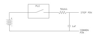
Anyway...I built a low pass filter, and it almost works great. I attached a pic of the circuit below, works great below about 400hz. Above that and the driver doesn't see any steps. Not sure why it is limited so low, I followed calculations from here: http://sim.okawa-denshi.jp/en/CRlowkeisan.htm
Does anyone have experience with this? Any recommendations for moving forward? I need more speed now! If I could get up to 1khz I would probably be happy!
One more question, does anyone know what the part number is for the high speed FET that AB uses?
Thank you for your time.
Joe

Last edited:


