I have another challenge with the program. I'm attempting to ensure that a range of input can be given as a setpoint and that any other input (such as negative or greater than the highest possible setpoint) is flagged as an error and zero is moved to the data register. I've completed the logic to compare and move zero to the data register, but my challenge is determining how to flag the error code either through the HMI or from the ladder program.
You are using an out of date browser. It may not display this or other websites correctly.
You should upgrade or use an alternative browser.
You should upgrade or use an alternative browser.
Programming Question
- Thread starter THIMMY01
- Start date
I assume you are using an HMI for operator input, I have never come across an HMI where an input field cannot be limited i.e. range for example limits to 0-100 or -10 - 75 etc.
So if you are then there is no need to write PLC code to limit it.
HMI's generally if the value put into a variable is outside the set limits it pops up an error message & does not change the value.
However, if using the PLC is the way you want to go then in the PLC just do a compare for > max or < min & if either is true then write 0 (or min) to the variable
---[> Dxxx K100]--------[MOV K0 Dxxx]
|
---[< Dxxx K0]-------+
I assume you are using an HMI for operator input, I have never come across an HMI where an input field cannot be limited i.e. range for example limits to 0-100 or -10 - 75 etc.
So if you are then there is no need to write PLC code to limit it.
HMI's generally if the value put into a variable is outside the set limits it pops up an error message & does not change the value.
However, if using the PLC is the way you want to go then in the PLC just do a compare for > max or < min & if either is true then write 0 (or min) to the variable
---[> Dxxx K100]--------[MOV K0 Dxxx]
|
---[< Dxxx K0]-------+
I am currently using the GT designer 3 to simulate the PLC program, I'm not using a real HMI yet. I have done the comparing and moving zero to the data register. I just want to know how I can give the error message through the simulator or PLC code.
For the "Quote" you included, how do I output strings (such as "error: a0000004x") from the PLC ladder logic? And how is it done in GT designer3?
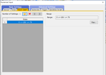
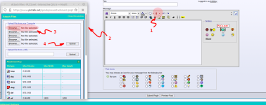
As I said you do not need to do it in the PLC see pics of GT Designer
You set the number of places on the input variable, go to Input case tab and there should be a pre-set limit 0 <= $W >= 100 just change the values to what you want, it's that simple second pic is the error message it shows on the HMI.
if you generate the error message in the PLC you could just use the alarm system or to add text to a variable then use the $MOV function
i.e. [$MOV "abc123" D100] However, you must be aware that ascii chars could be 64 chars long so could use D100 to D163


Last edited:
You are right. It worked perfectly well. But I will still like to know how to output strings with the PLC code.
When I tried to simulate a message popped up, saying
"Cannot start the monitoring because the FB instance is not selected. Please execute again after selecting of FB instance. Data Name: Alarm"
What have I done wrong?
When I tried to simulate a message popped up, saying
"Cannot start the monitoring because the FB instance is not selected. Please execute again after selecting of FB instance. Data Name: Alarm"
What have I done wrong?
drbitboy
Lifetime Supporting Member
I'm assuming you mean using GXWorks to monitor an instance of a FB, this cannot be done as GXWorks does not interact with the GT software as such, also monitoring a PLC the PLC cannot tell GT what is being monitored.
Also is there a reason you have more than one instance of a FB, often this way of using an FB is it creates the code for the amount of instances, most only use FB's as one instance & pass the parameters to the one instance i.e. there is only one bit of code for the FB, it passes the user parameters to local variables & works on those. in essence more than one instance creates separate bits of code for each instance.
Also is there a reason you have more than one instance of a FB, often this way of using an FB is it creates the code for the amount of instances, most only use FB's as one instance & pass the parameters to the one instance i.e. there is only one bit of code for the FB, it passes the user parameters to local variables & works on those. in essence more than one instance creates separate bits of code for each instance.
The answer to your question regarding a message in GT Designer is simply a text field, just give it the number of characters you need & in the PLC use the $MOV function so for example:
-----| |------[$MOV "asdfghhjkl" D100]
That will display that text in the text field on the HMI.
-----| |------[$MOV "asdfghhjkl" D100]
That will display that text in the text field on the HMI.
I'm assuming you mean using GXWorks to monitor an instance of a FB, this cannot be done as GXWorks does not interact with the GT software as such, also monitoring a PLC the PLC cannot tell GT what is being monitored.
Also is there a reason you have more than one instance of a FB, often this way of using an FB is it creates the code for the amount of instances, most only use FB's as one instance & pass the parameters to the one instance i.e. there is only one bit of code for the FB, it passes the user parameters to local variables & works on those. in essence more than one instance creates separate bits of code for each instance.
I created two Function Block, and I'm using the two in the MAIN POU. Though I deleted an FB earlier that I wont be needing. But right now its two FB that I am using in the MAIN POU. Can this be the problem?
The answer to your question regarding a message in GT Designer is simply a text field, just give it the number of characters you need & in the PLC use the $MOV function so for example:
-----| |------[$MOV "asdfghhjkl" D100]
That will display that text in the text field on the HMI.
Oh okay, thanks.
Similar Topics
I'm been deciphering a program for a press here. I've gotten most of it deciphered using the manual to understand the instructions (first mitsu...
- Replies
- 11
- Views
- 286
Hello. Was just curious, if it is possible to load an image from an SD card on to a Compactlogix PLC that came straight out of the box brand new...
- Replies
- 4
- Views
- 545
Hi All,
Looking for advice on programming MicroLogix 1400 with RSLogix500.
Basically, I have a client who requested I make a "simple" program...
- Replies
- 19
- Views
- 3,214
How do you code it to when you push a button attached to X001, it turns on Y001. Then, the next time you push the button attached to X001 it...
- Replies
- 4
- Views
- 1,611
I am just finishing up my project, which was my first experience with PLCs. I thank everyone that has helped me work through the RIO and analog...
- Replies
- 11
- Views
- 2,967


