Programming Question

I had an additional thought: if the logic resets the counter on the scan when the counter reaches 4, then if the counter trigger is still 1, it may count to 1 on the next scan.

The way to avoid this would be to postpone the reset until the counter trigger (X001 below) returns to 0 after the counter reaches 4.

X001 K4
-----] [----------------(C0 )----

C0 X001
-----] [-----]/[--------[RST C0]-----


Counters usually only work on rising edge so probably no need, never seen a counter that would count every scan if enable is true.
 
What is this all about ? Which task is it that has to be solved with this combination of control ?
And what is the context ? Is it for studying or is it a real project ?
 
Counters usually only work on rising edge so probably no need, never seen a counter that would count every scan if enable is true.

I understand and agree that is how counters work in normal counting, but that was not why I did that. My concern was that the RESET instruction would also erase the counter's internal "memory" of its input rung's state, and so, on the next scan after counter completion triggered the RESET, the counter could "see" a rising edge of its input rung.

this is about how reset of a counter works, not how a counter counts.
 
Counters usually only work on rising edge so probably no need, never seen a counter that would count every scan if enable is true.
I never said every scan, just two successive scans across a reset.

See this link: https://drive.google.com/file/d/124pHBCPhmTGrFF1Jo4tu64KQSa7Fci8A/view?usp=sharing

(I'm not always right, but it does usually work out that way ;))

I apologize for the poor quality and Moire effects.

Of course, that does not mean OP's system will work the same way, but it is summat to watch out for.

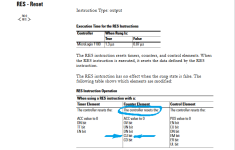
P.S. see the MicroLogix 1100 manual here: https://literature.rockwellautomati...documents/rm/1763-rm001_-en-p.pdf#G12.1049214

which explains that behavior, specifically:

xxx.png
 
Well I just tried it on a ML1400 & it does not count, it needs the enable to go false then true again, this is also true on Mitsubishi, not tried any others as I do not have the hardware.
 
I had an additional thought: if the logic resets the counter on the scan when the counter reaches 4, then if the counter trigger is still 1, it may count to 1 on the next scan.

The way to avoid this would be to postpone the reset until the counter trigger (X001 below) returns to 0 after the counter reaches 4.

X001 K4
-----] [----------------(C0 )----

C0 X001
-----] [-----]/[--------[RST C0]-----


When I used the logic, it worked perfectly. Thank you very much.
 
Well I just tried it on a ML1400 & it does not count, it needs the enable to go false then true again, this is also true on Mitsubishi, not tried any others as I do not have the hardware.

Sorry @parky, I am not being clear; what you did there does not address the issue I raised.

I an NOT saying the counting trigger (that sets the CTU input input rung true) needs to be a one-shot; I understand that is is likely that the counter of every PLC brand only counts rising edges.

I AM saying, when the counter accumulator reaches the preset so the count is complete (e.g. in MicroLogix C5:0/DN becomes 1), that using that DONE bit to enable a RESet/RST/... instruction to make the counter start over again counting from zero will cause the counter to count from 0 (after the reset) to 1 on the very next scan.

Try the program from this video on your ML1400, and let's see if the two counters stay in sync or not.
 
QUOTE: I had an additional thought: if the logic resets the counter on the scan when the counter reaches 4, then if the counter trigger is still 1, it may count to 1 on the next scan.

That's what you said & as I pointed out if the trigger is still at 1 after a reset on the next scan it will not count, however, I believe the problem is that as the reset is directly after the count when it reaches 4 it will instantly reset so any logic before or after (assuming using the .DN bit or checking for C = 4).
So the simplest way is to reset the counter after the use of the DN bit or a compare.
Interesting though, I did a quick bit of logic in ladder where the counter was reset before using the equivelent of the .DN bit to set a Bit, when the counter value equalled 4 the counter reset so the bit was never set, when the reset was moved after using the .DN bit to set a bit it worked as expected (no surprises there), however,
I did the same logic using IEC Counters (these have a reset in the block call so it seems to indicate that it would reset the equivelent of the .DN bit before it was used to set the bit), however, it did not so no matter whether you evaluate the DN bit before or after a reset (you can reset the counter external to the counter function).
It appears (well in Mitsubishi) the IEC counter function works differently than the standard timer in ladder, cannot try it on ML1400 as it does not have IEC counters.
See attached picture (reset after evaluating the .DN bit equivelent).

Count.png
 
drbitboy said:
I had an additional thought: if the logic resets the counter on the scan when the counter reaches 4, then if the counter trigger is still 1, it may count to 1 on the next scan.
That's what you said & as I pointed out if the trigger is still at 1 after a reset on the next scan it will not count,

What @parky pointed out is incorrect, at least on MicroLogix, as demonstrated by my video

I understand that the two rungs as shown, one right after the other, leave no opportunity to detect, or act on, the counter reaching the preset, but that is because those two rungs are only a test to prove that the reset causes another count on the next scan without an actual rising edge.
 
Last edited:
Here is a MicroLogix 1100 program, save from its running state, showing that not waiting until the counter trigger goes false causes an extra count, so a counter preset of N will complete after only (N-1) actual rising edges of its trigger.

I understand this is not an IEC timer and this behavior may be specific to MicroLogix 1100 and/or RSLogix Micro Starter Lite/500, so YMMV.
 
Hello, I am trying to use a digital to analogue converter module Q64DAN, and an optocoupler for PLC to arduino connection in other to send word variable to the arduino as setpoint. What will be the ladder logic in the gxworks 2 and the connection settings? I have tried to check Q64DAN manual, but I have not still been able to get the ladder logic right.
 
Assuming you are using GXDeveloper go to PLC Parameter, select the slot where the card is going then select intelligent 32 points then press the select key, then select the Q64 DAN Then select the type of output i.e. 4-20ma 0-5 0-10 etc. & save your project, you will need to download the project to the PLC including the PLC Parameter then you need to create a little bit of program to send the value to the card. using the U\G commands these send the data to the correct channel buffer memories. If you were using GXWorks2 then it is easier by configuring the address of the data to send I have sent you a PM.
 

Similar Topics

I'm been deciphering a program for a press here. I've gotten most of it deciphered using the manual to understand the instructions (first mitsu...
Replies
11
Views
283
Hello. Was just curious, if it is possible to load an image from an SD card on to a Compactlogix PLC that came straight out of the box brand new...
Replies
4
Views
544
Hi All, Looking for advice on programming MicroLogix 1400 with RSLogix500. Basically, I have a client who requested I make a "simple" program...
Replies
19
Views
3,214
How do you code it to when you push a button attached to X001, it turns on Y001. Then, the next time you push the button attached to X001 it...
Replies
4
Views
1,611
I am just finishing up my project, which was my first experience with PLCs. I thank everyone that has helped me work through the RIO and analog...
Replies
11
Views
2,965
Back
Top Bottom