Hydraulic Pressure Control (Hydraulic Design)

Taylor Turner

Member
Join Date
Sep 2020
Location
Midwest
Posts
78
I want to share a trick and see if anyone can do better!


With hydraulic presses there is a point at the beginning of the actuator movement when it's pressing against air and the part/tooling has not been met yet. Then when the part/tooling has been met by the actuator, a big nasty pressure spike happens. How can we handle this?


I always have a programmed slow down position to allow a full throttle start; Customers always have a cycle time. A regenerative circuit is enabled at this point in time. Then at a position, the regen circuit is disabled and the analog pressure reducing valve is reduced to an appropriate pressure to meet the part/tooling. PROBLEM! acceleration is in the equation F=MA. You still get a pressure spike. I thought I was wise to just extend as slow as I possibly can and gently, perfectly meet the part; Customers always have a cycle time. It is always too slow.


I need high velocity and low force, so how can M be as small as possible?
Hit the part in regen at the low pressure analog signal.


The mass/pressure will be reduced by the ratio of the cylinder's cap and rod side areas and in turn the rod side will act against the cap side.


I have had hydraulic circuits that are riddled with relief valves to catch pressure spikes, but this has the best result I have seen in application. Nothing special, but is there better?


PS: I monitor velocity to kick out of regen an start the pressure control.
 
I want to share a trick and see if anyone can do better!

With hydraulic presses there is a point at the beginning of the actuator movement when it's pressing against air and the part/tooling has not been met yet. Then when the part/tooling has been met by the actuator, a big nasty pressure spike happens. How can we handle this?
I thought the senior people there would have told you about this.

This is a key thing to remember.
When the press is coming down it has potential and kinetic energy. You can't do much about the potential energy mgh. However, you can do something about the kinetic energy (1/2)m*v^2

When contact is made the kinetic energy is converted into work forming the part. That is the integral of force x distance. This means if the kinetic energy is high then wither the force or distance or both will be high to absorb all that kinetic energy.

What to do.
1. SLOW DOWN!
Slow down just before impact so you have just the right amount of kinetic energy to form the part. The kinetic energy is proportional to the velocity squared so slow down by half reduces the amount of kinetic energy by 1/4.

2. The peak force can be reduced if the distance over which the force is applied is increased. This is why presses have cushions. A hard rubber mat will absorb energy too and is simpler than using a cushion.

Now about #1.
The problem with slowing down rapidly is that the cylinder may cavitate. Also, if is possible that the natural frequency of the platen and cylinder is not high enough to slow down very fast.

I wrote a lot about this in the 2020 year of H&P magazine.

It is all about matching the energy supplied to the energy required so not much energy if left in the form of a pressure spike.


I always have a programmed slow down position to allow a full throttle start; Customers always have a cycle time.

good
A regenerative circuit is enabled at this point in time.
Not when decelerating? Clarify this.


Then at a position, the regen circuit is disabled and the analog pressure reducing valve is reduced to an appropriate pressure to meet the part/tooling. PROBLEM! acceleration is in the equation F=MA. You still get a pressure spike. I thought I was wise to just extend as slow as I possibly can and gently, perfectly meet the part; Customers always have a cycle time. It is always too slow.
Regen is OK when retracting back up but not when going down or applying force.


I need high velocity and low force, so how can M be as small as possible?
Hit the part in regen at the low pressure analog signal.
You need two pressure signals. One for the cap side and one for the rod side. Force=Pa*Aa-Pb*Ab
When in regen the controller has no control of the flow coming out of the rod side. No braking! Yikes!


The mass/pressure will be reduced by the ratio of the cylinder's cap and rod side areas and in turn the rod side will act against the cap side.
Think more in terms of force.


I have had hydraulic circuits that are riddled with relief valves to catch pressure spikes, but this has the best result I have seen in application. Nothing special, but is there better?
Relief valves are NOT fast enough. Relief valves are safety devices not control devices. There are better options.
 
Last edited:
I thought the senior people there would have told you about this.


The problem is apparent here, but not the solution


What to do.
1. SLOW DOWN!

I'll tell that to the people that only say SPEED UP!


Regen is OK when retracting back up but not when going down or applying force.

I don't think it's possible to retract with a common regen circuit. The cap side pressure is equal to the area of the rod. That's why when pressing against something force is so low and velocity is fast.

You need two pressure signals. One for the cap side and one for the rod side. Force=Pa*Aa-Pb*Ab
When in regen the controller has no control of the flow coming out of the rod side. No braking! Yikes!


All force moves start with an open loop move. Starting a force move before meeting the part is like whisky throttle.
 
The problem is apparent here, but not the solution

I'll tell that to the people that only say SPEED UP!
Yes, but there is this thing call physics. Where is all that kinetic energy going to be dissipated? Ask your hydraulic/mechanical designers.


I don't think it's possible to retract with a common regen circuit. The cap side pressure is equal to the area of the rod. That's why when pressing against something force is so low and velocity is fast.
I really didn't think so because the rod side piston are is so small. However,using regen means the RMC is not controlling the rate of deceleration during closing. So ask your clever hydraulic designers who is controlling the deceleration during regen.


All force moves start with an open loop move. Starting a force move before meeting the part is like whisky throttle.
????


The RMC has a openloop decel to a position. It just a linear ramp in the control output as a function of position. This still doesn't consider that the cylinder will cavitate when decelerating too fast and that the RMC has NO control of the oil going out the rod side when in regen.


Taylor needs to have a serious talk with his mechanical and hydraulic designers. The regen idea is a bad one. I know it is meant to save energy but the energy it saves is going into pressure spikes/heat so the energy isn't really being saved.


I understand that reducing cycle time is a priority. Try moving up the platen/slider just high enough to get parts in and out. Saving on stroke length saves a lot.


About the pressure spike. Try small accumulators between the valve and the cylinder. This is normally a BIG NO NO. The trick is to pressurize the accumulators to above the system pressure. The bladder in the accumulators must not squeeze through the end of accumulator when you do this. Now, under normal conditions, there will be NO oil flowing in or out of the small accumulator which is good because it won't interfere with motion control. However, should a shock occur the pressure spike will be absorbed by the small accumulator thus saving your pressure sensors. Also, after the spike is done the energy in the accumulator is returned to the system. This trick works very good on planner press rolls.
 
Although I don't work with hydraulic presses (our other plant does though), I have had to overcome similar challenges with having to avoid pressure spikes. And yes, the customer (internal) always wants it to go faster.

With our setup, we are cycling a hydraulic valve on a test part (part-under-test). I have to apply various pressures to the valve on the test part (87, 145, 260 psi), and of course the customer always wants to cycle the valve at >= 3 s/S cycle rate (the absolute fastest it physically can go). It typically has to cycle for 2M cycles or part failure, whichever comes first. Of course, there can't be any pressure spikes, or as little as possible. The 'nasty' pressure spike happens when the valve piston on the test part bottoms out. Without having a means to know where exactly that is, I found it to be extremely challenging to control those pressure spikes at that speed. It was akin to driving in pitch darkness at 70 mph and there's a solid cement wall somewhere out in front of you, but you have no idea when you're going to smash into it, and then when you do smash into it, you have to be able to brake without damage to the car. Based on the reaction time of the servo valve being used and the Delta, the math says both together are fast enough to control those spikes. Still, I had a hell of a time, and it doesn't help that the part-under-test works loose (breaks in) over thousands of cycles and that makes the initial tuning values invalid. Typically on a new test part after I get it tuned and running, I have to keep periodically adjusting the tuning values over a few hours until the test part is fully "broke in".

Fortunately for my sake and my application, there is a way to know when the valve on the test part is close to bottoming out. The valve on the test part mechanically rotates a metal ring on the part. I use a prox switch mounted on the part to detect when that ring has rotated x-amount of degrees, then I know the valve piston is just about bottomed out. That's when I switch to closed loop pressure control. Maybe or maybe not the best way, but it works.
 
We do all sorts of tests at Delta in order to learn more. One test we did was to slam a very heavy object into the end of a cylinder rod and try to control the force. What we found is that the RMC would respond instantly because we had fast pressure sensors. The control output out go to negative 10 volts because the pressure was increasing. However, it took many milliseconds for the valve to respond so there was always a pressure spike.


In saw mills there are machines called 3 or knee carriages.
https://www.lumbermenonline.com/items/76303/RAW_McDonough Carriage DSC_2363.jpg
Logs roll onto the carriages and hit the knees that position logs through the saws. There are sometimes huge pressure spike depending on how big the log is and how fast it is moving. The logs are often being scanned before they hit the knees. This gives the knees a chance to start retracting before impact kind of like a base ball catcher retracting his glove when catching fast balls. My point is similar to basarider29's, it is impossible to stop instantly without using a lot of force.


Again it amounts to knowing where does all the energy go!
BTW, McDonaugh is a customer too.


@busarider29, are you really interested in pressure or force? Can you share what your are testing? We get involved in many testing applications.
 
Peter,

Yes, I can share. I have some images a drew up a few years ago that describe the test setup and components used. I'll find them and post next week. The part under test is a one-way controllable clutch that installs in the transmission of the vehicle. We've had the clutch in production for a few years now. If you drive a Ford, there's a high probability that this one-way controllable clutch is in your vehicle.

It's pressure that we are controlling. We use a pressure transducer (TD1000) on either side of the valve on the test part for feedback. There is a Moog servo valve that is used for proportional control of the fluid to the test part's valve.

The other applications that the Delta will be used are for spindle machines (to be built this year), where we will just be controlling the speed of the spindle and its accel/decel rates. One of those machines will have two opposed motors that must be tightly synced. Both motors will be independently controlled but speed synchronization (+- 1 RPM delta max over entire speed range (0-20K rpm) is absolutely critical.
 
However,using regen means the RMC is not controlling the rate of deceleration during closing. So ask your clever hydraulic designers who is controlling the deceleration during regen.


Trying to program in a position for a decel when you're expecting force is a nightmare. If you're off by a couple thou it sometimes means tens of tons punched on the part and god forbid the preformed part be inconsistent.


I do think I left a detail out that may be contributing to your opposition. Consider that the pressure control is not with a +/-10V valve at the cylinder but a 0-10V valve at the pump.


Regen should never be intended to control any consequence of position. Take the linear out of the equation and only when the cylinder is in regen and the initial time that position velocity is zero. There is still a pressure spike at the initial time that position velocity equals zero, but it is only that of the area of the rod's diameter.


On an agreeable note I do like accumulators when it comes to force control. Never have had one between the valve and the cylinder though. I'll have to go test that!
 
Trying to program in a position for a decel when you're expecting force is a nightmare. If you're off by a couple thou it sometimes means tens of tons punched on the part and god forbid the preformed part be inconsistent.
You have no hope when the cylinders is in regen and the RMC isn't controlling the flow out the rod side. How can the RMC do any braking?


I do think I left a detail out that may be contributing to your opposition. Consider that the pressure control is not with a +/-10V valve at the cylinder but a 0-10V valve at the pump.
How far is this pressure control valve from the cylinder? Do you know it takes about 1 ms for the pressure wave to travel 4ft? What is controlling the pressure control valve?


Regen should never be intended to control any consequence of position. Take the linear out of the equation and only when the cylinder is in regen and the initial time that position velocity is zero. There is still a pressure spike at the initial time that position velocity equals zero, but it is only that of the area of the rod's diameter.
Regen is a no-no if you want precision.


On an agreeable note I do like accumulators when it comes to force control. Never have had one between the valve and the cylinder though. I'll have to go test that!
Make sure you pressurize if above the system pressure.


Have you met Jason Palmer, our technical sales guy? He is good. He use to work for JHF before working for us.
 
You have no hope when the cylinders is in regen and the RMC isn't controlling the flow out the rod side. How can the RMC do any braking?


Minimal pump pressure during regen is sufficient "braking." Braking to a position and expecting force is fortune telling. The open loop decel makes perfect sense, but it should still work with this regen. The valve should never cross under zero and introduce pressure to the rod side.


How far is this pressure control valve from the cylinder? Do you know it takes about 1 ms for the pressure wave to travel 4ft? What is controlling the pressure control valve?


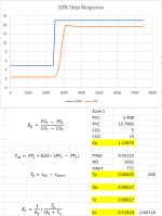
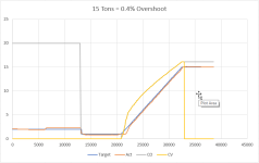
This application specifically, it's a country mile, with flex hose, a dreadfully slow pump, and a check valve on the cap side so the pump can be shut off for a 7 hour dwell. Ha. That's another can of worms. When pressure bleeds off to an amount the pump kicks back on for another pressure ramp. Think about the target generator and initial values for that re pressurization... nightmare. Attached is the step data and first pressure ramp control. I know is it FOPDT and insufficient for needs of the few.

Step.PNG Control.PNG
 

Similar Topics

Hi All, I could do with some advice on a hydraulic control system. It is necessary for me to accurately position a vertical hydraulic ram with...
Replies
34
Views
1,892
Hi, I am looking into a project to build a control system for a hydraulic test machine. Working with hydraulics is not something I have done...
Replies
10
Views
3,598
I am working on a control for a press (the riggers dropped the control panel off a truck) that was all manual control. I have been able to get...
Replies
4
Views
3,363
Goodday, Has anyone ever seen a pressure transducer that can provide 2 analog outputs?? Looking online, but not too many that I can find. The...
Replies
6
Views
2,661
I had posted an earlier thread about a scale w/parameters issue. Turns out it may not be the issue. Since, I do not have much PLC experience, nor...
Replies
23
Views
7,001
Back
Top Bottom