PLC & Schematic

mitch11

Member
Join Date
Mar 2017
Location
Ohio
Posts
26
I've got an extremely basic question regarding PLC's and the design schematics...
Note: RSLogix5000

How do the coils/contacts within the PLC program line up with those found in a schematic for a design. For instance, you see NO & NC contacts going into an input card on a schematic. Will these same NO & NC contacts be reiterated in the logic of the program?

May be a confusing question but I'm struggling to see if there is any correlation between the contacts on a schematic and the contacts within the logic.

Thanks!
 
When you say schematic, are you talking about actual paper drawings of say a control layout?
Or are you talking about what you see on your laptop screen while programming in RSLogix 5000?
 
The first of the two. Like a drawing package for an entire system. I understand how contacts and coils work and everything, just never done any programming.
 
I have never seen N/O and N/C contacts drawn onto input cards of a controls schematic.
Do you have any examples of what you are talking about that you could post.

When you say you know how contacts and coils work, are talking about you know how to wire relays and coils with wire?

Or are you saying that you actually know how the contacts and coils work in a PLC ladder program but you have just never actually done it yourself?

Sorry to answer your question with more questions, but I want to make clear what it is you do and don't understand and exactly what it is you are looking for before putting forth any answer.

BCS
 
Did not hear back from you, I am a few hours behind Kentucky so you probably turned in for the night. I am going to take a shot at explaining some simple instructions and hopefully we will be on the path to what you are asking. If I am then we can build off this. If I am not then you will have to explain better what it is you are looking for.

I have never seen N/O and N/C symbols represented on input cards of a schematic. Could you be talking about N/O and N/C switches in a circuit that control power to the input card terminals? Maybe I am not understanding what you are saying but lets see if this will help make things a little more clear.

----] [------------------------( )

Above represents what you are calling a N/O contact, this is actually an XIC (Examine if Closed Instruction) and an Output at the end of the rung.

Lets assume we are using 24vdc sinking inputs.
When there is no voltage applied to the input its value in the data table is 0, but when you apply +24vdc to this input, its value is changed from a 0 to a 1, which makes the input instruction True. If you are online with the processor you will see a green bar illuminate across the instruction.


---]/[-------------------------( )

Now lets look at what you are calling the N/C instruction, this is actually an XIO (Examine if Open Instruction)

Lets assume this the exact same input as before but we have just changed it from an XIC to and XIO in the ladder program.

Now if there is NO voltage going to the input, the value in its data table is 1 the instruction is True. If you are online with the processor you will see a green bar illuminate across the instruction.
If you +24vdc to the input this XIO instruction will have a data table value of 0.......even though the input has power.

This is exactly opposite of the XIC instruction.

So now you see that the same exact Input Tag can be True if there is power at its corresponding input or not, depending on what instruction we use for the input in the ladder logic.

If the instructions to the left of the output on a rung are all True (1) then the output will put a 1 in its bit box (data table value). It will be True and the output will be active.
If you are online with the processor you will see a green bar illuminate over the instruction in the ladder program.

Without going into detail I just want to say that there are also other kinds of inputs, some that do not require input cards at all. We can get into this later if this conversation is headed in the right direction.

I am going to stop here and let you respond. I tried to keep the explanation simple and if this is starting to help answer your question and it seems like I am on the right track to what you are asking, let us know and there is plenty of building we can do off of this.

If this is way off from what you are asking then let us know that also, so we can go in a different direction.

BCS
 
Last edited:
No problem with asking me additional questions! And I would just like to say thanks for all of the help you have provided! I really appreciate it.

I understand it's a difficult question to answer, but I just wasn't sure how to ask it due to my inexperience with RSLogix, etc.

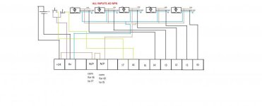
So I have attached an image of an example of what I am confused about. In the image there are 2 NO contacts to relays just before going into the Input Card. Would these same NO contacts be seen within the ladder logic (as XIC) in the appropriate rung? Or are these additional conditions that must be met for voltage to be present at the input?

The way I am understanding this scenario now is... if the Master Control Relay is energized, the NO contact prior to the Input Card will be closed and power will be present at the input. Therefore, an XIC will illuminate green within the ladder logic and an XIO will not illuminate. Is this correct?

Hopefully this makes things a little more clear!

Thanks again.

PLC.jpg
 
The way I am understanding this scenario now is... if the Master Control Relay is energized, the NO contact prior to the Input Card will be closed and power will be present at the input. Therefore, an XIC will illuminate green within the ladder logic and an XIO will not illuminate. Is this correct?

Yes. You understand it correctly. If the correct voltage is present at the input terminal, the bit that stores that information will be a "1" and will light up green on the online monitor when "examine if closed" instructions reference it.

Some good basic info here:

https://www.youtube.com/watch?v=zlsJxSK8tPE

Watch the videos in order and it should give your PLC education a kick start.
 
It sounds like you are comprehending it correctly now, but let me explain what I see in you diagram and hopefully it will make things even clearer for you.

The green blocks to the right are your digital inputs on an input module in your plc.

Input #6 (or 05) on that card will get energized when N/O contacts 5 & 9 of CR154401.12 close.
I am assuming this is an auxiliary contact on a circuit breaker.....lets just go with that assumption for now.

Using the above, when you turn on the circuit breaker for your panel fan, N/O contacts 5 & 9 close and voltage becomes present at input #6 (05) of this input card.

Now the corresponding data table for this input #6 (05) will now have a value of 1.
What you would do with this in the program will be totally up to you to suit your needs.

Lets say you want to use this input to turn on an inducator light so you know the breaker is on. Then it would look like this.

---] [-----------------( )

The XIC (Examine if Closed) is your input tag and the output would be tagged to correspond to the output you wired your indicator light to.
There would be a green illuminated bar across the XIC when voltage is present on the physical input. So this instruction looks to see that there is a data table value of 1 for this instruction to be true.


If you wanted to turn on a Fault Indicator Light if the breaker tripped instead. Then it would look like this.

----]/[-----------------------( )

The XIO (Examine if Open) again is your input tag and the output would be tagged to correspond to the output you wired your indicator light to.
There would be a green illuminated bar across the XIO when voltage IS NOT present on the physical input. So this instruction looks to see that there is a data table value of 0 for this instruction to be true.

So you see, you do not necessarily need an input to physically have voltage going to it, in order to make an output true.
In the programming you can say, if this input does not have voltage then make my instruction true by using the XIO instruction.

If the instructions to the left of the output are true, then the output will write a 1 into it's data table value and the output will be true. The physical output will energize and your indicator light will come on.

If you have not already, go to Youtube and search for Ron Beaufort Plc videos or PLC Bootcamp videos.
Watch these and they will help you understand better than I can explain it.

Don't be shy to ask questions though, there are a lot of very great people here that are more than happy to help you.

Good luck
 
Last edited:
Thank you so much for your help! I really, really appreciate it and feel that I have much better understanding now.
 

Similar Topics

Hello, fairly new to plcs I’m tasked with installing a PE to a micrologix1200, in the attached picture I/14 is the PE I’m installing it’s going to...
Replies
6
Views
942
E
My most immediate concern is how to represent my PLC (inputs, outputs & logic) in my electrical schematic that I need to provide to my customer...
Replies
2
Views
11,302
Can we possibly show a simple schematic for a basic plc? :rolleyes:
Replies
4
Views
3,705
Good Day to all of you, this is my first post, i will try to explain as best as possible, english is not my natural language. I am performing an...
Replies
0
Views
19
Hi All, Someone at work has put a PLC system on my desk, that's just been taken off an idle production line. He said "It's an S7 PLC. We don't...
Replies
3
Views
80
Back
Top Bottom