
brendan.buchan
Member

Hi all, this is my first post here.
I am an industrial electrician but have done some PLC courses and basic programming.
A client of ours is building a new additive system for their process line, and wants us to do the program.
Basically, I need to control the flow rate (l/min) of an additive depending on the product type selected, and the speed of the product being extruded (cuts/min).
I have a SEW variable speed drive controlling the pump, an ABB flow meter will be giving me my flow rate, and the average cuts/min is already being calculated and used in the existing program.
I have done the logic already, but I have never used the PID instruction before.
I just want to know if I am on the right track, or if there are still things I am missing or doing incorrectly.
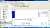
FLOW_METER_L_MIN will be the analog flow meter converted to L/min
DRIVE_SUGAR_PUMP_SPEED_SET will be the analog speed signal being sent to the drive (I am not sure what unit or format this has to be in yet, I still need to research the drive)
There is logic set up to move the appropriate flow rate required to PID_SUGAR_SYSTEM.SP depending on the average cuts/min.
Is there anything else I am missing?
How will the PLC know how quickly to ramp up the speed of the drive depending on the setpoint compared to the current flow rate? Will it need to run through some sort of tuning?
What format will DRIVE_SUGAR_PUMP_SPEED_SET be in from the PID instruction?
Thanks in advance for any help.
Click to view full size!
I am an industrial electrician but have done some PLC courses and basic programming.
A client of ours is building a new additive system for their process line, and wants us to do the program.
Basically, I need to control the flow rate (l/min) of an additive depending on the product type selected, and the speed of the product being extruded (cuts/min).
I have a SEW variable speed drive controlling the pump, an ABB flow meter will be giving me my flow rate, and the average cuts/min is already being calculated and used in the existing program.
I have done the logic already, but I have never used the PID instruction before.
I just want to know if I am on the right track, or if there are still things I am missing or doing incorrectly.
FLOW_METER_L_MIN will be the analog flow meter converted to L/min
DRIVE_SUGAR_PUMP_SPEED_SET will be the analog speed signal being sent to the drive (I am not sure what unit or format this has to be in yet, I still need to research the drive)
There is logic set up to move the appropriate flow rate required to PID_SUGAR_SYSTEM.SP depending on the average cuts/min.
Is there anything else I am missing?
How will the PLC know how quickly to ramp up the speed of the drive depending on the setpoint compared to the current flow rate? Will it need to run through some sort of tuning?
What format will DRIVE_SUGAR_PUMP_SPEED_SET be in from the PID instruction?
Thanks in advance for any help.
Click to view full size!


