rslogix 5000 - newbie doubt

kuppe35

Member
Join Date
Nov 2020
Location
italy
Posts
15
Hi all,
I'm quite new to the automation world. I've used a bit Tia Portal in the last month and now i have a new working in rslogix 5000.
From the client excel table i have some ON-OFF contactor with only one digital Output for each one. (many of these are for enlightenment btw)
On the HMI panel I have already preconfigured a green/red led to monitor the status and an OPEN and CLOSE button to comand the contactor.
On the PLC side I've created a ladder AOI to manage their logic.
All I want to do is:
-if I press the hmi close (open) button the contactor will close (open).
-if for same case the PLC goes down the contactor must not be modified.
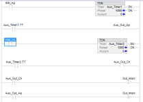
Here's what i've thought. It could go well?
(Ap=Open , Ch=Close btw XD)

interr.PNG
 
Hi and welcome to the forum. I'm not sure if this is homework; if it is, then so far this is what I would do: I don't use OTL's and OTU's unless absolutely necessary. So to not cause trouble I believe there was a long discussion about this a few months back. I guess it's just personal preference and my boss at my last job didn't want to use them at all. I always try to use holding circuits. Anyway, one can use a flip-flop circuit to change the state of an output basically on one rung with a momentary PB. You can research flip-flops here on this forum. Hope this helps and good luck!!
 
Just read your post and cannot quite fathom out what you are trying to do, you appear to say that if you press a button then a contactor pulls in (Energises) in other words latches, however, you also state if the PLC goes down then you do not want the state of the contactor to change i.e. it stays energised, if this is what you expect then it will not happen, when a PLC detects an error then it will switch all outputs off so the contactor will de-energise. The only other way would be to latch it outside of the PLC. I may be wrong but that is how it reads to me.
It sounds to me that this sounds like it is an upgrade from a manual starter i.e. it has a start/stop built in.
 
I see two issues:

1) I don't think that the program shown in the OP is going to work as expected.

For example, consider the following sequence of events, starting will all tag values being 0 (Out_Interr contactor is open),and the timers not timing

1.1) The operator performs the first action on the HMI CHIUDERE (CLOSE) button

1.1.1) HMI_Ch will change to 1 (PLC Input scan); on the next PLC Program Scan:
1.1.1.1) Aux_Timer2 will start timing (Rung 2)
1.1.1.2) Aux_Timer2.DN will be (stay) 0 for up to 5 seconds of time
1.1.1.3) Aux_Timer2.EN will change from 0 to 1 (Rung 2)
1.1.1.4) Aux_Out_Ch will be latched to 1 because of Aux_Timer2.EN (Rung 2)
1.1.1.4.1) I.e. as long as HMI_Ch is 1
1.1.1.5) Out_Interr will be latched to 1 (Rung 3)
1.1.2) N.B. (Nota Bene) Out_Interr will continue to be latche on every following PLC Program Scan
1.1.2.1) as long as Aux_Out_Ch is 1, and
1.1.2.2) the timer is not done
1.1.3) Because Out_Interr is now 1, the physical contactor will close

1.2) After 1 second of time, and before Aux_Timer2 completes, the operator performs the second action on the HMI CHIUDERE (CLOSE) button

1.2.1) HMI_Ch will change to 0 (PLC Input scan); on the next PLC Program Scan:
1.2.1.1) Aux_Timer2 will stop timing and reset; (Rung 2)
1.2.1.1.1) Aux_Timer1.EN will become 0
1.2.1.1.2) Aux_Timer1.DN will never become 1
1.2.1.2) The Aux_Out_Ap value will stay at 1 because it was latched (Rung 2)
1.2.1.2.1) Even though Aux_Timer2.EN is 0
1.2.2) N.B. Out_Interr will continue to be latched to 1 on every following PLC Program Scan (Rung 3)
1.2.2.1) Because Aux_Out_Ch is 1, and
1.2.2.2) the timer will never complete (Rung 2)
1.2.3) Because Out_Interr remains 1 and Aux_Out_Ap is 0, the physical contactor stays closed

1.3) Sometime later the operator performs the first action on the HMI APRIRE (OPEN) button

1.3.1) HMI_Ap will change to 1 (PLC Input scan); on the next PLC Program Scan:
1.3.1.1) Aux_Timer1 will start timing (Rung 1)
1.3.1.1.2) Aux_Timer1.DN will be (stay) 0 for up to 5 seconds of time
1.3.1.1.3) Aux_Timer1.EN will change from 0 to 1 (Rung 1)
1.3.1.1.4) Aux_Out_Ap will be latched to 1 because of Aux_Timer1.EN (Rung 1)
1.3.1.1.4.2) I.e. as long as HMI_Ap is 1
1.3.1.1.5) Out_Interr will be unlatched to 0 on Rung 4
1.3.1.1.5.1) N.B. However Out_Interr is still being latched to 1 on Rung 3
1.3.1.1.5.1.1) Because Aux_Out_Ch is still 1 because it was latched on Rung 2 and never unlatched
1.3.2) N.B. this will continue happen on every PLC Program Scan as long as HMI_Ap is 1
1.3.3) The physical contactor will usually be opened on the PLC Output Scan, because the Aux_Out_Ch value is 0
1.3.3.1) N.B. However, if the PLC Output Scan interrupts the program Scan between Rung 3 and Rung 4,
1.3.3.2) Then the physical contactor will be closed
1.3.3.3) Because Out_Interr has a value of 1 between Rung 3 and Rung 4
1.3.3.4) And this could happen on every other scan

1.4) The operator does not perform the second action on the HMI APRIRE (OPEN) button for at least 5 seconds of time

1.4.1) Aux_Timer1 will complete, (Rung 1); on that same scan
1.4.1.1) the Aux_Timer1.EN value will remain 1 (Rung 1)
1.4.1.2) the Aux_Timer1.DN value will become 1 (Rung 1)
1.4.2) Aux_Out_Ap will be unlatched to 0 (Rung 1, lower branch)
1.4.3) Out_Interr will be latched to 1 on Rung 3, because Aux_Out_Ch will still be 1
1.4.4) Out_Interr will no longer be unlatched to 0 on Rung 4, because Aux_Out_Ap will remain 0
1.4.5) The physical contactor will be closed, and stay closed, because Out_Inter will stay 1

That is only one possible scenario. This is a case of "The only thing worse than a program not doing what you want, is when it does what you told it to do."

2) The desired behavior when the PLC goes down:

-if for same case the PLC goes down the contactor must not be modified.
[N.B. I would appreciate if someone with more experience would confirm what I am saying here (Update: @parky already confirmed this):]

I do not believe that desired behavior, to maintain contactor state if the PLC goes down, will happen in the current design, because the Out_Interr output will become 0 if the PLC mode is changed or the PLC is powered off, which will open the contactor. The latch on Out_Interr to 1 only retains, and returns to, its previous state when the PLC is comes back up, e.g. after a power (on => off => on) or mode (Run => Program => Run) cycle.

If it is desired to maintain the physical contactor state when the PLC goes down, there will need to be an external physical seal-in circuit e.g. see http://www.contactandcoil.com/patterns-of-ladder-logic-programming/startstop-circuit/. That would also require two PLC outputs per contactor, because the external circuit cannot distinguish between the output becoming 0 from operator action vs. the PLC going down. That said, if there was a way to detect externally whether the PLC was up or down, there should be a way to wire some external logic to use only one PLC output to achieve the desired behavior.


to close => chiudere
to open => aprire
contactor => conttore
switch => interruttore


Caveat

The problem statement does not say whether the HMI command button is a toggle button or momentary button. I assumed it is a toggle button, that is, the operator performs one action to turn it on so its tag (HMI_Ap or HMI_Ch) value becomes a 1 in the PLC and stays that way, and they perform a second action to turn it off so its tag value becomes a 0 in the PLC. The second action may be identical to the first (e.g. press the same spot on the HMI) and it is only the ordering that determines if it puts a 1 or a 0 into the PLC tag value. It does not matter above if it is actually a momentary button (press and hold to put and keep a 1 in the PLC tag value; release to put and keep a 0 in the PLC tag value).
 
Adding to that, is the "remote starter" one of two things a mechanical button arrangement that toggles based on two buttons that are mechanically linked or is it a panel or starter where the two buttons control the local power to the coil just like a start/stop button arrangement.
On the latter loss of power to the starter will stop it anyway, so what is the difference in the PLC loosing power?.

On another note: What about safety, has the customer thought about this ?.
I really think you need to find out what this unit you are going to control is, how it currently works & if it is safe to do it this way under current laws in place. Remember, any modifications must comply with current legislation and you would be responsible if it caused an injury.
I suggest you give us some idea as to why this is required, the reasons for this etc.
 
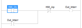
I do not recommend it, but the ladder code shown below is similar to your OP code, without having the problems mentioned earlier.

interr.PNG


I think the next is a slightly better option, assuming

  • only one output per contactor is available, so you give up the "do not modify contactor if PLC goes down" requirement, and
  • you want to latch the outputs, so a PLC that goes down and comes back up will return to it's previous state
    • N.B. THIS HAS SEVERE SAFETY IMPLICATIONS BECAUSE THE PROCESS COULD RETURN WITHOUT WARNING TO ITS PREVOUS STATE ON A PLC POWER LOSS/RESTORE CYCLE, WHICH COULD RESTART MOTORS AND/OR RE-ENERGIZE CIRCUITS SOMEONE IS WORKING ON.
    • For this reason it is generally considered a bad practice to latch an output.

yyy.png


But of course the best would be everyone's favorite bog standard Start/Stop circuit:


zzz.png


Then you could use the State Coil/Fault Coil pattern to implement the external physical "do not modify contactor" logic with only one additional output total for the project, instead of one additional output per AOI which additional output

  • Is always 1 when the PLC is up
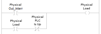
  • holds all contactors in their current state when the PLC is off, using the following EXTERNAL PHYSICAL circuit:
aaa.png


N.B. that might need a physical de-bounce (pulse extender) on the on-to-off transition of [Physical Out_Interr], to handle the transition.


The PLC-internal ladder logic for the single, process-wide [PLC Is Up] output is extremely simple:


Code:
              PLC
             Is Up
--------------( )-----
 
thanks for the answer. I will modify the code as yours. I didn't mention at first that the button on HMI shoud be momentory, so 1 only when HMIbutton is pressed. I need to use the timers to be sure that the plc doesn't lose the pulsed due to asynchronism between plc and hmi
 
There are two issues with momentary 1s sent from HMIs:

  1. Is debounce (slug) needed? Not because the HMI comms will have bounce, but to avoid acting on an unintentional touch by the operator.
    1. To deal with this, tie the HMI_Ap/Ch bits to timers, as you did originally
    2. Use the Timer_Ap.DN and Timer_Ch.DN bits in the on/off logic.
    3. Tell the operators they need to hold the momentary in for the duration of the timer i.e. until they see the load stop or start.
  2. The HMI may not reliably assign 0s to the HMI_Ap/_Ch bits when the button is released; this may be what you meant by "asynchronism between PLC and HMI."
    1. The way to deal with this is to unlatch the HMI_Ap bit whenever the output is 0, and unlatch the HMI_Ch bit whenever the output is 1.
      1. The pulse has been detected and acted on, and is no longer needed.
    2. This is called "set it and forget it."
 
Just read your post and cannot quite fathom out what you are trying to do, you appear to say that if you press a button then a contactor pulls in (Energises) in other words latches, however, you also state if the PLC goes down then you do not want the state of the contactor to change i.e. it stays energised, if this is what you expect then it will not happen, when a PLC detects an error then it will switch all outputs off so the contactor will de-energise. The only other way would be to latch it outside of the PLC. I may be wrong but that is how it reads to me.
It sounds to me that this sounds like it is an upgrade from a manual starter i.e. it has a start/stop built in.

What you say is not strictly true, but there are some considerations ....

The OP used the phrase "the PLC goes down". He needs to elaborate as to what he means by "the PLC".

In Logix5000 you can configure the Output modules to behave how you want, for the following scenarios ....

A. The controller goes into Program Mode (specifically, "Not-Run" mode. You can choose, for each output bit, whether the bit goes off, comes on, or retains its last state.

B. The controller module Faults. You can choose, for each output bit, whether the bit goes off, comes on, or retains its last state (they call it "Hold").

C. The output module loses its "connection" to the controller (comms lost) while it is the "Program Mode" state. You can choose whether the outputs stay on the "Program Mode" state, or switch to the "Faulted" state.

Caveat : Those above are referring to the controller module as "the PLC", in other words the output module is still functional. But if the OP means "everything" as the PLC, then there is no way you are going to keep an output on when it "goes down".

To achieve what he says he wants, external latching will be required, and that opens up another can of worms over that dreaded word - "safety". A risk assessment will be required if the control system is not totally in charge of the outputs. e.g. what happens if the PLC "goes down", and there's no-one in the control room to even notice it ?
 
Dabba I do understand that, however, it is not the sort of thing I would suggest unless there was a safety issue on a pump stopping on PLC fault, in general unless the above scenario I would let the watchdogs/ PLC errors shut off all outputs and if it is required there be other methods of safety (backup systems).
Like you say, if the module is faulty then it would stop the pump or what ever, this scenario has appeared for me a number of times especially on ovens, in those cases the product belt had two drives, one run from the system and a backup DC drive with battery backup to drive the oven belt to remove product to prevent a fire.
 
I have done something like what you are asking for in the past - many years ago, but I can't remember why.

I wanted a Ladder subroutine to execute just once more after it's call went false. Sort of like a "post-scan".

I seem to remember this is how I did this, and you can use "Routine_1_Active" in the post-scan to do whatever you need to do.

I don't see why it can't be used for any language of subroutine....

2021-02-03_154952.jpg
 

Similar Topics

Hi all, sorry for the stupid question but I've been spending an hour to understand why some simple lines of code don't work. I'm in Rem Prog...
Replies
13
Views
2,486
Hey guys great site! Anyway I'm working temporarily over my winter break for a company. Basically I just get to mess with some of their plc...
Replies
12
Views
21,278
Hi folks, in the alarm manager of Rslogix 5000, the tag-based alarm has been created. But when I tried to change the condition, it was found the...
Replies
0
Views
21
I am completely stuck on building a ladder program that requires a start button to be pressed 3 times to turn on motor 1. Then motor 2 starts...
Replies
20
Views
528
Back
Top Bottom