Loop a Shift Register and Delete individual bits

mejadiaz

Member
Join Date
May 2020
Location
San Juan
Posts
9
Hello,
Its my first time working a project that involves PLCs. I need to develop a way to track parts with serial numbers that are passing through a conveyor. The tricky part is that it is a cyclical conveyor. The parts may stay on the conveyor for more than one cycle before they are picked up to be moved to the next part of the process. I have 18 nests and I need to keep track of their position and of what part is loaded on the nest (if any). I will also be tracking the picked up parts. There will only be a sensor where parts are loaded and picked up (specific nest locations).

So far I am looking at shift registers to keep track of the loaded nests in the conveyor. Each bit in the shift register would be a specific nest location. However, ideally the shift register would not wipe the bit in the last position after an indexation, it would place that bit in the first bit of the shift register. Is this possible? Also, is there a way to clear specific bits in the shift register, instead of resetting the whole register? Is there another way to do this that I desire? Perhaps the solution is not exactly a shift register, but something more advanced. The other issue I have is how do I relate the bit in the shift register with the part ID. Any help is greatly appreciated.
 
I am using a CompactLogix and I haven't started writing the program yet (in Step Ladder Logic). I have only developed a flowchart of what should be the sequence, routines and the "IF"s for the whole cell program. Thank you.
 
It wouldn't be a bit shift register it would be numeric. Use a numeric array. Make it one longer than the number of locations. Use a COPY command to shift the information.


You have 18 nests so make the array at least 19 (0 - 18) long. Just before shifting copy location 0 into location 19. Then do COPY array[1] array[0] 18.


An array location's content would be 0 if the nest is empty. To load just write the part_id into the array location you designate as the load position (I assume no part has an id of 0).


To unload just set the appropriate array location for that unload position to 0.


I don't have RSLogix5000 available so I can't provide actual code but these ideas may get you going.
 
I wouldn't use a shift register of bits. I would use an array with and index and offsets and in your case, serial number. This is the technique we used for lumber sorters. Sometimes the lumber would have to recirculate because a bin, what you call nest, was full and no other empty bins were available. We used modulo arithmetic because the index register plus the event offset could try to access data beyond the array.


Are there distinct places or intervals on the conveyor? Lumber sorters had lugs that would push the individual pieces of wood on the chain.
If not then you need to keep track of each piece by an encoder count and keep track of counts to the next event.
 
I think it would be ideal to give some idea of what the part number consists of
For example, it may be possible to incorporate the part no. & if a nest is occupied & if it has done more than one loop.
But we need to know more information for example, I did a similar system on a pick & place machine that assembled telephone push button switches many years ago. although it did not use actual part numbers, I only used one shift register but the information was contained in the 16 bit word. The lower byte contained the part ident (used to determine what nest would place a part in the base component). The upper byte was used for information on a number of things using the bits. each bit represented a certain function i.e. bit 8 was part not removed first time bit 9 was used for part not removed second time, bit 10 was used for part not removed 3rd time (Stop machine). The other bits were for error checking for example a part was not placed in a nest (reject essentially). I cannot remember all the functions but essentially the lower byte used for part no. upper byte used for reject or part in nest for more than 1 rotation. As for re-entering the last word back into the shift register, this was quite simple, I just populated the first with the last (I think it was a little bit more complicated but that was the essence of it) I do believe the shift register was one word longer than the number of nests this was required as essentially the loading nest for the base part would have to except a part that was already in place. The no part in nest was a 0 in the word this indicated there was no parts so no population of other parts etc.
I do not have RSL so I will leave this to others to give you some guidance some may have other ideas like using more than one shift register (especially if the part number will not integrate into the one shift) and there will be plenty of ideas from people who use RSL a lot more than me.
 
I wouldn't use a shift register of bits. I would use an array with and index and offsets and in your case, serial number. This is the technique we used for lumber sorters. Sometimes the lumber would have to recirculate because a bin, what you call nest, was full and no other empty bins were available. We used modulo arithmetic because the index register plus the event offset could try to access data beyond the array.


Are there distinct places or intervals on the conveyor? Lumber sorters had lugs that would push the individual pieces of wood on the chain.
If not then you need to keep track of each piece by an encoder count and keep track of counts to the next event.

There are fixed positions on the conveyor. Every time it indexes the nests will move to the same position the previous nest was located. Specific positions will be for loading or unloading. These positions are fixed. What can change is how many nests are indexed on one movement command. A part may need to go to the offloading position regardless of where it is on the conveyor, so it would be indexed directly to the offloading position. Which would mean that more than one shift has occurred.
 
In that case then (I'm just guessing what happens) you would need to have an index pulse for movement from one nest to the next i.e. even if it continued without stopping (as you say may skip nests to go strait to unloading station).
This to be honest seems a little strange if a part is required to go strait to de-nest, what happens to the ones behind they will have to go round again seems a bit of a waste of production ?.

Ideally this would not be the case, the thing is the conveyor will be feeding more than one process and different part numbers will be loaded. I need to feed the machines as soon as they ready to receive a new part. The process itself is complex because of this reason and that the parts loaded will be random. I am programming for the extremes, so that under the most expected scenario it will perform well.
 
I think it would be ideal to give some idea of what the part number consists of
For example, it may be possible to incorporate the part no. & if a nest is occupied & if it has done more than one loop.
But we need to know more information for example, I did a similar system on a pick & place machine that assembled telephone push button switches many years ago. although it did not use actual part numbers, I only used one shift register but the information was contained in the 16 bit word. The lower byte contained the part ident (used to determine what nest would place a part in the base component). The upper byte was used for information on a number of things using the bits. each bit represented a certain function i.e. bit 8 was part not removed first time bit 9 was used for part not removed second time, bit 10 was used for part not removed 3rd time (Stop machine). The other bits were for error checking for example a part was not placed in a nest (reject essentially). I cannot remember all the functions but essentially the lower byte used for part no. upper byte used for reject or part in nest for more than 1 rotation. As for re-entering the last word back into the shift register, this was quite simple, I just populated the first with the last (I think it was a little bit more complicated but that was the essence of it) I do believe the shift register was one word longer than the number of nests this was required as essentially the loading nest for the base part would have to except a part that was already in place. The no part in nest was a 0 in the word this indicated there was no parts so no population of other parts etc.
I do not have RSL so I will leave this to others to give you some guidance some may have other ideas like using more than one shift register (especially if the part number will not integrate into the one shift) and there will be plenty of ideas from people who use RSL a lot more than me.

As for the part numbers, they consist of 9 numbers and a dash between them. I was thinking I could assign each part number (they are not a lot) to a number and manage a single number in the arrays for each part on the conveyor.
 
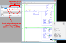
Proof of concept below, coaxing FFL/FFU to make a FIFO shift register act as a cycling buffer.


HOWEVER, I agree with PeterN: the buffer should be fixed and not move, and the index of one of the spots where transactions can occur (part removed, part added) should be kept track of. So even though the transactional spots are fixed and the conveyor nests move, the program models the conveyor nests as fixed (in the buffer) and the world rotates around the conveyor. At the top of each scan, one transactional spot is set to its current nest, and then the rest are set from that. E.g. say you have three transactional spots, A, B and C, and they are evenly spaced around the conveyor, one every six nests. So if the 18 nests move from A to B to C then back to A, the program models that as spot A moving down in nests. So if A is at nest 8, then B is at nest 14 ((8 + 6) modulo 18), and C is at nest 2 ((8 + 12) modulo 18). And if the conveyor then advances 10 places, then spot A will be at nest 16 ((8 - 10 + 18) modulo 18), B at nest 4 ((16 + 6) modulo 18), C at nest 10 ((16 + 12) modulo 18).

xxx.png
 
Hi, as far as setting and clearing individual bits in a shift register in your logix processor, you would use the latch and unlatch output instructions (OTL and OTU, respectively). That way, the data is essentially saved and properly passed when the bit shift instruction is executed. Just be sure to consider the sequence - latch/unlatch before indexing or index then latch/unlatch - don't let it happen by chance (a race condition), so that you have a deterministic data flow, otherwise, you may alter information in the wrong location.


Regarding your project, are you de-nesting to different locations based on the part number? Are you indexing this conveyor by use of a motor contactor/VFD along with an index sensor to know when to stop, or are you using some motion control system (stepper, servo)? Do you need to retain the dashes in the part number? Do you want to store any information besides the part number to pass along to whatever the function the part will go to?


I am asking these questions to better familiarize us with your project, because if this is your first project with PLCs (as you mentioned), then you may have many followup questions. The answers to my questions will allow us to help you better.
 
As for the part numbers, they consist of 9 numbers and a dash between them. I was thinking I could assign each part number (they are not a lot) to a number and manage a single number in the arrays for each part on the conveyor.


Exactly: create a string file (array); each index number into that string file represents that part number; this also makes it easy to add new part numbers i.e. at the end of the string file.


The ugliest part of the code will be the lookup from part number (string) to index number, but that can be put into an AOI or subroutine; the next ugliest bit will be finding which nest contains a given part.


Meanwhile the index numbers of the actual parts are kept in the integer file that models the nests of the cyclical conveyor.


It's all just bookkeeping, really.
 
Hi, as far as setting and clearing individual bits in a shift register in your logix processor, you would use the latch and unlatch output instructions (OTL and OTU, respectively). That way, the data is essentially saved and properly passed when the bit shift instruction is executed. Just be sure to consider the sequence - latch/unlatch before indexing or index then latch/unlatch - don't let it happen by chance (a race condition), so that you have a deterministic data flow, otherwise, you may alter information in the wrong location.


Regarding your project, are you de-nesting to different locations based on the part number? Are you indexing this conveyor by use of a motor contactor/VFD along with an index sensor to know when to stop, or are you using some motion control system (stepper, servo)? Do you need to retain the dashes in the part number? Do you want to store any information besides the part number to pass along to whatever the function the part will go to?


I am asking these questions to better familiarize us with your project, because if this is your first project with PLCs (as you mentioned), then you may have many followup questions. The answers to my questions will allow us to help you better.

Yes, I am de-nesting to different locations based on the part number, yes. We will be indexing the conveyor with a servo motor controlled by the PLC. I do not need to retain the part number as it comes, I will only be reading the part number to know to where it will be de-nested. I would like to store information on the quantity of parts that passed through the conveyor with x part number and how many failed or passed the next process. The machine that will receive it will give me a signal letting me know if it passed or failed. I will not pass this information on however, it will be stored in the PLC.
 

Similar Topics

Hi, I'm quite new to Rockwell PLC and currently trying to implement the following if Sw1 then for i:=1 to 20 by 1 do xEnable := 1...
Replies
4
Views
132
Hi all, I'm connecting several 4-20mA sensors together in parallel (only one shown below) The enclosure is ABS plastic with metal backplate DAQ...
Replies
5
Views
260
I have always controlled servos in Rockwell motion using position loop. I have an application where one process will push against a servo...
Replies
3
Views
262
Hello All Could we get some expertise on flow control ? -Using a PID loop in Productivity 2000 with an analog output, How can we convert...
Replies
19
Views
1,562
Complete noob here, using a Click C0-02DD1-D to run a test stand. Requirement is to turn on motor run for X seconds, turn off and dwell for X...
Replies
6
Views
1,064
Back
Top Bottom