MODBUS on micrologix 1400 and Multiranger 100

Phillyblunz

Member
Join Date
Jan 2013
Location
Edmonton Alberta
Posts
15
Hello everybody! I'm new here so let me know if there is a way to find this stuff already.

I am working with a PLC program and the customer wants to change from DNet to MODBUS for communication between the PLC and Multiranger 100.

I am trying to set up the MSG blocks to make this work and was hoping for a bit better guide then the 1400 ref manual.

Basically how many files do I setup in the PLC if I only require a single reading from a single device?

A MSG block I know, but what about EQU and MOV blocks? Do I need them to get the reading from the Miltronics?

All I want to do is take the measured water level via MODBUS and place it in a data table.

The DNet setup somehow got the reading from a non-existant analog register.
Then it used a MOV block to place the level reading where the normal analog reading gets moved too, this gave redundancy if the DNet failed.

Now they want me to remove the analog altogether and only use MODBUS with no redundancy.

Tell me what else I need to tell you guys so you can help me out a bit.

So far I have created a program file called "LAD 9 - MODBUS"
Within I have a single rung with a MOV block on it.
I have setup a Data file called "MG10 - MODBUS"
Within the MG10 - MODBUS file is a series of parameters and it seems the only option is a binary entry of all data from here on out.
I am unsure of these parameters settings.

What is the easiest way to get the reading via MODBUS to the PLC?

Cheers!!
 
You need four things to start with:

1. The port configuration. Choose the Channel 0 or Channel 2 serial port and configure it for Modbus RTU Master, with the appropriate serial speed and framing values to match the Multiranger. If you're using RS-485 instead of RS-232, we'll look at that later.

2. The Message control data file. You've created MG10, and you're going to use one element of that data file for each MSG instruction you put in the program.

3. An Integer data file. This is where the MSG instruction will put the data payload it reads from the Multiranger. Choose any existing N-type data file that has enough room, or create a new one specifically for this purpose.

4. The MSG instruction. You need to fill in the blanks in this Instruction with the MSG control block element, the port number, the message type, the Data Table in "This Controller", etc. There are quite a few fields but they should all make sense.

Don't attempt to manually fill out the MG10:x elements; use the configuration window that appears when you click "Setup Screen" in the MSG instruction block.
 
I've only messed around with a few drives on modbus.
This is how I set it up. I am reading and writing multiple parameters. Disregard the enable bits. These drives were screwy because if you powered one down, it shut down the other two.

It's almost self explanatory. Ken listed the requirements.

One question. Rung 3 is the MSG. For only 1 parameter, do you need rung 4 associated with it? Haven't tried it yet.


mbus_zpsbd964163.png
 
1. Done.

2. I intend to use a single MSG so I guess use MG:10.0 (Is this right?)

3. Done created N11 - MODBUS

4. So this is what i have filled in for the "Setup Screen"
(Under "This Controller")
Channel = 0 (Using channel 0 on RS-485)
Modbus Command = 04 Read Input Registers (Or do i want to use "03 Read Holding Registers?)
Data Table Address = MG10:0/0
Size in Elements = 16 (For double integer I would think)
(Under "Target Device")
Message Timeout = 2 (Default, not sure if this needs to change)
MB Data Address (1-65536) = ?
Slave Node Address (dec) = ?
Modbus Address = 30001

What info do I need to fill in those couple of fields? Would this be something from the Multiranger 100 manual?

How do I post pictures or scans of the manuals on this forum? Do I need to create a photobucket account?
 
Paddies I dont have the same screen as you posted.

I guess that means I am wrongly using the 04 Read Input registers option, I will change it to 03 read holding registers and change my element size down to 1, then set the data to 16 bit as you have.

I still need to know what the MB data address is and slave Node address is.

I assume the slave node address will be one if I only have a single slave device?
 
Change the "Data Table Address" under "This Controller" to the actual Integer data table that you want the Modbus data to go into, like "N7:0".

The MG10:0 element is just to store the status and configuration of the Message, not the data payload.

The number of "Elements" is the number of Integer data table words. If you're literally reading just one Modbus Holding Register, this should be 1.

You probably want to use Function 03, "Read Holding Registers".

The Multiranger user manual will describe the Modbus Address. It might call it out as "holding register number" or as "4000x". The "4" is like "N" in the A-B world... it means "this is a holding register" rather than "Forty Thousand and X elements".

Holding Registers are the most common way to encode data over Modbus. But the Multiranger manual will tell you for sure.

The Multiranger's Modbus Slave node address is probably configurable. Most of the time this will be "1" in a single-slave system.

When you're using Channel 0 on the MicroLogix 1400, set up the port configuration Handshaking parameter for "485 Network - No Handshaking". This enables Pins 1 and 8 (RS-485) instead of the other RS-232 pins. The 1763-NC01 wiring adapter is indispensable for this connection.

RS-485 always has a third wire for the signal common. Sometimes the shield or ground is used (a bad practice, but frequently done) and sometimes it gets its own conductor. Make sure you account for this in your physical connection to the Multiranger.

For testing, just put a test bit (like B10:0/0) in front of the MSG instruction. I can deliver my stern lecture about the perils of automatically-retriggering MSG instructions later.
 
I am not sure what is going on, the N11:0 I choose still shows 0 but my multiranger shows a level of 1.6 meters.

1. I am using port 0 for the multiranger 100 to communicate with the PLC.

2.I have created the MG10, but am not sure what to do now to as you say "going to use one element of that data file for each MSG instruction you put in the program"
Not sure how to go about doing this or choosing which bit from MG10 and where to put it.

3.I created N11:0 to store the MODBUS data but it still shows 0. I have gone into the "Setup screen" and choosen N11:0 as the data file.

4.I am unsure where this takes place, is this the setup screen in the actual MSG block?


Also the MB data address is still set at 1 on my PLC, should this change? I see the picture posted uses 10 here for what-ever reason. How do you know what value to enter here?

Thanks a bunch for your support here guys, this forum is a great resource and I hope to use it a bunch in the future.
 
If you can post your program file it might help. ZIP it before attaching it.

You're using MG10:0 as the "Control Block". All you have to do is make sure MG10 exists, and enter "MG10:0" in the MSG instruction in the ladder editor, in the "MSG File" field.

Even though you're only reading 1 word now, the N11 data file ought to be bigger than 1 element to allow for testing and future expansion; open the Data File properties and make it 10 or 20 elements. You've got plenty of memory.

You do all the configuration right there in the "Setup Screen". Directly changing things inside the MG10:0 control block is an advanced technique: everything you need to change is available from the Setup Screen.

The rung containing the MSG instruction has to go from False to True every time you want the MSG to execute. For testing, I always put a single B3:x/y bit in front of the MSG so that I can manually trigger it and watch for the /DN or the /ER bits to come on.

I don't use Multiranger 100's so I don't have a user manual handy. You should be able to figure out how to set the Modbus Node Number, as well as the serial framing (baud rate, data bits, stop bits) on that device.
 
Hey I think I have it sorted out now.

It was a dumb mistake. I made a new program rung but did not create a jump to subroutine to activate it.

Now I have a value in my N11:0 and just need to create a scaling block so I think I am in control of the situation now.

Thanks for your help, I will come back and post again if I get stuck again, or I have complete success.

Cheers.
 
Oh and I just have the MSG block on a rung by itself, should I place a timer on on it so it triggers once every 10 seconds or so?

What if I just leave it "On" all the time? Its time for the lecture you mentioned earlier, LOL.
 
I've seen a lot of programs that use the automatic-retriggering logic that padees posted above.

And there's nothing inherently wrong with it, especially if you have a very solid physical network.

But because it re-triggers a MSG instruction just as soon as the previous one has finished, it heavily loads the controller CPU with messaging, leaving less bandwidth for it to communicate with HMI or programming terminals, and increasing scan time a little.

And once you get more MSGs than buffer spaces (it depends on the controller and network port), a few message failures can cause a cascading backup of the communication buffers and "lockup" of communications on the controller.

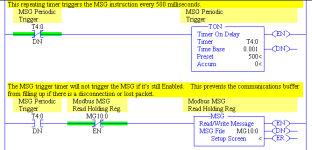
The simplified method that I prefer is to use a self-resetting Timer to produce a periodic /DN bit, which is used to trigger the MSG. Every time the Timer reaches preset, the MSG will be triggered once.

In addition, I use the /EN bit of the MSG itself as a condition of the MSG rung. This prevents the triggering timer from re-triggering the MSG while it's still pending completion (which will fill up the buffers).

The MicroLogix 1400 has a single-message buffer for Modbus and will reject any MSG instructions that are triggered while one is still pending a reply, so that /EN bit isn't strictly necessary. But it's never too early to learn good programming practice.

MSG Trigger Example.png
 
We never allow more than message at a time. DN OR ER bit of the previous message triggers the next. I've never seen a total message stoppage on a network which is normally working. Typically we are talking to a group of Powerflex drives. We've had up to 15 drives with a read and write message each. Even if if the network connection is totally removed at a drive there is simply the pause for timeout on those two communications then it continues around again.
 
It is a success!

Thanks again to you all.

Hey Ken is there a way to give credit on these forums for helping me out?

Some forums have a "say thanks to...." option.

Cheers.
 
Hi Ken Roach,

Thank you for the guidance on setting ML1400 as modbus master.

However, I still had another problem with Micrologix 1400 as modbus master.
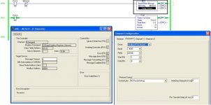
I was trying to connect Micrologix 1400 as modbus master with Floboss S600+ as modbus slave through RS-485 (using 1763-NC01 at port 0)
I've done all the steps that you mentioned in the previous post.
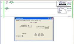
The problem is the Micrologix didn't receive any message from Floboss.
(please see attachment)

Do you have suggestion on this problem?

ML1400_modbus_master.jpg channel_status.jpg
 

Attachments

  • TEST MODBUS.zip
    11.6 KB · Views: 194

Similar Topics

I want to learn about modbus communication and I saw on another thread about inexpensive modbus relay units so I found it on Amazon along with a...
Replies
46
Views
7,223
I have a spare Micrologix 1400 Series B I bought used on Ebay awhile back. I had thought of it as a spare PLC for my train project but I screwed...
Replies
4
Views
1,254
Good Day! Would anyone be able to explain what is happening with the COP's and MOV's in this Modbus poll routine? If anything I am confused by...
Replies
6
Views
1,731
I been tasked with setting up communication between a heating cooling unit manufactured by Advantage Engineering and a Microloagix 1400 plc. The...
Replies
6
Views
2,507
Hi, I am trying to communicate between a MicroLogix 1400 and a Click PLC. There is a great video from AD that shows the simplicity of...
Replies
2
Views
1,765
Back
Top Bottom