PID loop tuning

Ones_Zeros

Member
Join Date
Feb 2014
Location
at work
Posts
367
Hello Everyone,

I have a fast PID loop that I was having issues with tuning it.

- The CV is a sliding stem valve
- The PV is a High pressure transmitter.
- Valve closes when pressure gets above the SP

I have the control action of the PID correct, but where the gas
pressure is high coming into the valve. I can’t seem to get the tuning
correct to keep the valve from going from all the way closed to 100% open.

I need to have the valve to operate in a manner to where it’s not going closed to slamming all the way open. It seems if the pressure gets a little above the SP it will control move smoothly but during start up when the pressure is high the valve gets a work out. I don’t think the valve will last long like this.

I have my “P” and “I” settings low and my question is for a fast loop like this should the P & I settings be higher?

I’m no PID loop tuning expert and everything I read seems to confuse me more.
I do appreciate the help

Thanks
 
Last edited:
What environment e.g. what PLC, what instruction?

Is it possible that meanings of the P or I settings are inverted from what you think they are e.g. a small proportional band is a large gain, and a small integral time constant is a large integral gain (repeats-per-minute)?

E.g. compare the meaning of Ki vs. Ti in the Independent and Dependent Gains Forms of the PID equation on page 3 of the document at this link.
 
Last edited:
Off hand, sounds like your tuning is too aggressive.

LOL.

That's dry, Ken, very dry.

...
Loop update time.

+1; I'll bet it's that, my brother has come across a lot of PID loops with ridiculous integral time constants (1e-3 minutes).

Also, OP mentioned that there is a problem at startup: please define the conditions at startup (e.g. PV far from SP; flows are low or high, etc.).
 
Also, define "fast" - seconds, milliseconds?


And the sliding stem valve: what kind of port (gate, globe, equal percentage, etc.)?

Is it loud i.e. is there (some term here like "sonic: that I forget) flow when the control is poor?


Ah, I remembered: critical flow.
 
I would start with just the proportional gain. The pressure will change as a function of the integral of the net rate of flow. Ones_Zeros is only controlling the input. Also, the flow will be proportional to a formula similar to this
Code:
Q=Kv(CV)*sqrt(P[sub]in[/sub]-P[sub]out[/sub])
where:
Kv is the valve flow function. Basically it yields so much flow per CV. Most valves are not linear so this is a non-linear function. If the valve was linear one could write:
Code:
Q=Kv*CV*sqrt(P[sub]in[/sub]-P[sub]out[/sub])
The flow through the valve will also be proportional to the square root of the pressure drop.
The rate of change of pressure is
Code:
dP/dt = β*(Q[sub]in[/sub](t)-Q[sub]out[/sub](t))/Volume
Where:
β is the bulk modulus of the gas.
Qin(t)is the flow into the pressurized volume down stream
Qout(t)is the flow out if the pressurized volume down stream.
Volume is the down stream volume of gas that is pressurized.


From this one can model the system pretty well. From this you can ask for information not yet provided. Otherwise you are just guessing or using trial and error.
 
Last edited:
You guys worry about the understanding the PID when you should be worrying about understanding what you are trying to control. If you don't understand what you are trying to control then how can you find an optimal control solution. I agree you can find something that works well enough using trial and error.

drbitboy is doing his job. He is pulling teeth. However, he should look at what I wrote and ask more/better questions. However, I doubt Ones_Zeros will be able to answer some of them.


Honestly, I don't see why people are told to tune systems like this that don't understand the complexity. On top of that the people that told Ones_Zeros are probably clueless too. I feel bad for Ones_Zeros because he has been thrown into the trenches with little information or training.


You can also try tuning software. PidBot is good to use, integrates nicely into Ignition. Both honor an unlimited two hour demo.
The flow through the valve may not and probably is not linear and it is definitely a function of the square root of the pressure drop across the valve. Does PIDBot know about non-linear functions?


So, One_Zeros really should present this thread and my comments to his bosses and ask them if they know the answers or even the right questions.
 
but where the gas pressure is high coming into the valve. I can’t seem to get the tuning correct to keep the valve from going from all the way closed to 100% open.

...if the pressure* gets a little above the SP it will control move smoothly but during start up when the pressure is high the valve gets a work out.


* is that the PV pressure or the pressure coming into the valve?


Is the controlled valve feeding the reservoir (volume) where the pressure PV is measured, or is the valve draining the reservoir?

If the controlled valve is feeding the reservoir, what is the character and nature of the sub-system that drains it (e.g. compressed air tools)?

If the controlled valve is draining the reservoir, what is the character and nature of the sub-system that feeds it (e.g. air compressor)?

What is the ratio of the pressures on the upstream:downstream sides of the valve when the problem occurs?

If this is a PLC, can you post your code (all of it, not just the PID)? PDF would be best.

How big is the reservoir, and what is the maximum flow through the valve (I think this is the question @PeterN thinks I should ask;))?

What deadtimes are in the system e.g. time from PLC changing CV to valve stem moving to that position?

There have been many questions asked but no response by OP; without any answers, @KenM's initial off-hand response is the only possible and reasonable answer.
 
Last edited:
probably is not linear and it is definitely a function of the square root of the pressure drop across the valve. ...

If the non-linearity of pressure drop vs. flow is in play, then non-critical vs. critical flow may also be in play, the latter of which is linear with pressure drop across the valve.
 
Since there has been no followup, the forum can offer nobbut wild guesses, so here is mine:

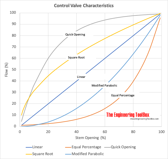
Non-linearity is the problem, and that in the flow equation contributes, but a bigger effect, and the primary reason the system is resistant to tuning, is the non-linearity in the CV to Cv relationship i.e. the valve characteristic.

Where

  • CV = PID output signal e.g 0-100%
  • Cv = valve flow coefficient; this is what should be in @PeterN's flow equations
I.e. it's a quick opening valve, and there is essentially no control if it opens beyond about 35-40% of stem travel, see the Quick Opening curve below; cf. here.

Control_Valve_Flow_Characteristics.gif
 

Similar Topics

Hello, I am attempting to tune a PID loop on a process. The process involves a valve with electronic actuator that has quite a high deadband...
Replies
10
Views
2,160
Hi all, splitting out from this thread because it's a somewhat different question to the original. I have to migrate some code from a Micrologix...
Replies
17
Views
4,069
Long time listener, first time caller. I have a Micro850 PLC controlling the temperature in seven fermentation vessels at a local brewery. Each...
Replies
2
Views
2,582
I am using PID instruction in RS Logix 5000 with independent equation. I am confused about its tuning. Please somebody explain under listed...
Replies
1
Views
4,921
Hi all, I'm working on this small batching project and this is my first time when i have to develop PID loop tuning screen on my HMI. I was just...
Replies
0
Views
1,690
Back
Top Bottom