A technique: an execution a bunch of commands cyclically

EStufC

Member
Join Date
May 2019
Location
Kikuara
Posts
69
Greetings!


S7-1500, TIA portal.


There's a need to control a few peripheral devices(smart sensors).

A command 'Out_1' says to device 1 "give output"
A command 'Out_2' says to device 2 "give output"
A command 'Out_3' says to device 2 "give output"
.
.
.
A command 'Out_99' says to device 99 "give output"

and again,

A command 'Out_1' says to device 1 "give output"
A command 'Out_2' says to device 2 "give output"
A command 'Out_3' says to device 2 "give output"
.
.
.
A command 'Out_99' says to device 99 "give output"

At the moment I have on my bench only two sensors for testing.
The current longest cycle time of PLC is about 12ms.
I'm afraid that such a bunch of polling peripheral devices just causes a wild slowing down of plc cycle.

My question is, perhaps anyone knows a technique how to do that by a proper way or more optimized way.

And generally is there a way to distribute the commands between plc scans (cycles)? So to speak, not to do that at a single scan.

BR
 
Last edited:
How is the data read from the device?

Even without knowing what's in the rest of the program, I doubt the scan time will grow linearly with every added device.
If you have two devices to test with, you could always test it by building the logic for the requests, but then use only those two outputs.

If you want to distribute the reading between several scans, you could add a counter to the logic and compare the counter's value to before enabling the output.

Here is pseudocode for it:

Out_1 := (counter == 1) AND (other_conditions == TRUE)
Out_2 := (counter == 2) AND (other_conditions == TRUE)
...
Out_99 := (counter == 99) AND (other_conditions == TRUE)

counter := counter + 1

IF(counter > 99) THEN
counter := 1
END IF


Edit: This would of course scan only one device at each program cycle, but nothing stops you from combining several devices to one scan by changing the compared value.
 
Last edited:
How is the data read from the device?


Good question, thank you.


The point is, besides "give out" I will have to execute one more command for interface module, so-called "Read".


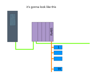
So it would look like as:


  • A command 'Out_1' says to device 1 "give output";
  • A command to interface module "Read";
  • An instruction Move measured value to a certain memory area;


  • A command 'Out_2' says to device 2 "give output"
  • A command to interface module "Read"
  • An instruction Move measured value to a certain memory area;


  • A command 'Out_3' says to device 2 "give output"
  • A command to interface module "Read";
  • An instruction Move measured value to a certain memory area;
of course in a infinite loop.


BR

bench.png
 
Last edited:
Are those Read and give output commands blocking? Or do you call them and wait for the function to tell you it completed successfully?

Since you're in Siemens, why not create an FC or FB that interacts with one device and does what you want, then see what is the parameter that will have to be changed and stick that as an input to the function. Considering your schematic, I guess it will be the address of the device.

If the functions to read the devices are blocking, you can bring out a flag to say the block completed and the logic above increments the address to the next device and moves on.
 
Are those Read and give output commands blocking? Or do you call them and wait for the function to tell you it completed successfully?


that's the point,
if judging on behaviour of these two sencors hanging on my bench, there should be used some kind of timing (so to speak, not more and not less time than it needs), due to the sensors just respond with a pure values. In other words there's no any confirmation saying "I've sent.The next one".


Since you're in Siemens, why not create an FC or FB that interacts with one device and does what you want, then see what is the parameter that will have to be changed and stick that as an input to the function. Considering your schematic, I guess it will be the address of the device.


there's no any problems to create a FC or FB. I have a lot of them in the project. The challenge is in technique or conception, as you wish.
 
Last edited:
What protocol are these sensors using? Are they responding via serial or is that RS-485 Profibus. I see now that I assumed it would be profibus and the values would just be ready to read.

If it's sent by Serial, I assume that the serial input on the PLC would buffer the received values, so if you know how the response from the sensor ends, you can just look for that value in the last received byte in the buffer.
I would also look at having a timeout on these, so if your answer doesn't come within a second or perhaps less, then throw an alarm.
 
What protocol are these sensors using? Are they responding via serial or is that RS-485 Profibus. I see now that I assumed it would be profibus and the values would just be ready to read.


There's no Profibus at all in this shematics.


If it's sent by Serial, I assume that the serial input on the PLC would buffer the received values, so if you know how the response from the sensor ends, you can just look for that value in the last received byte in the buffer.
I would also look at having a timeout on these, so if your answer doesn't come within a second or perhaps less, then throw an alarm.


The sensors are using pure RS485 protocol, I pointed it out on the picture attached. Yes, the RS485 implies itself serial data transmission.
 
Last edited:
There's no Profibus at all in this smematics.

Hence the use of the word assumed... I am somewhat dyslexic at times and RS-485 with that particular choice of color (the usual profibus cable color) for the module lead me to think in Profibus.

The sensors are using RS485 protocol, I pointed it out on the picture attached.
Interestingly, Profibus is in fact a protocol that runs on top of RS-485... whilst RS-485 isn't a protocol by itself.

Still, good luck solving your problem and sorry for taking up your time with my silliness.
 
Hence the use of the word assumed... I am somewhat dyslexic at times and RS-485 with that particular choice of color (the usual profibus cable color) for the module lead me to think in Profibus.


Interestingly, Profibus is in fact a protocol that runs on top of RS-485... whilst RS-485 isn't a protocol by itself.

Still, good luck solving your problem and sorry for taking up your time with my silliness.


never mind... and thank you for input!


P.S. RS485 has nothing to do with Profibus itself. Just 485 physical layer conception was taken by germans as a base for Profibus physical layer conception. That's all.


Moreover, many buses have similar physical layer organization.


BR
 
Last edited:
You wont have a problem with the PLC cycle time extending.

When you use a serial port in a Siemens S7 Project you must use the library block that are intended to be used with the serial module. This library block will work asyncronously. I.e. you send a command to the module, and then the library block will execute the command over several CPU cycles. The block will give you some status information for you to handle the sequence, typically "busy", "done", "error" or "status" or something like that.

Any which way, you can only send a command to a device at a time, and you also have to wait for each device to respond before sending the command to the next device.
So not only must you send data to the device, but you must receive the data and evaluate it.

I also assume you have to implement some kind of error handling. If a device doesnt respond within a certain time period, you should trigger an alarm and then send the command to the next device.
 
You wont have a problem with the PLC cycle time extending.

When you use a serial port in a Siemens S7 Project you must use the library block that are intended to be used with the serial module. This library block will work asyncronously. I.e. you send a command to the module, and then the library block will execute the command over several CPU cycles. The block will give you some status information for you to handle the sequence, typically "busy", "done", "error" or "status" or something like that.


here, you are right, in case when I use not third-party things.
That's a reason why I don't look in the direction of Step's SI library block. And I don't know whether it can be adapted or not.
In this shematics the only PLC from Siemens and other things have nothing to do with Siemens, due to customer's demands.
 
Last edited:
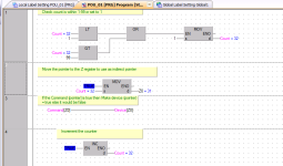
The problem in processing if a = 1 and xx = true is that you still have 99 lines being processed to check the if statements it would make sense if possible to indirectly address the tags. I'm not sure that this is possible in this case but if I wanted to only scan one bit of code point to them indirectly
(By the way I'm old school so my version is not actual ST code).

If Count < 1 or count > 99 then Count = 1 //Make sure counter is within limits
If A_Command [Count] = True then Device[Count] == true
Else Device[count] == False
ENDIF
Count = Count + 1
// so on each scan if Count is outside limits then set to 1 this ensures indirect addressing is not outside bounds. If indirect A_Command is true then set indirect Device to true else set it to false
Increment the count (this processes only one address each scan)
on next scan the count will equal Count+1 and so on, to scan more than one per scan just duplicate the code form If... to Count + 1 for as many ones you want to process each scan.
See code in GX Works

Indirect.png
 
You won't be able to have 99 devices connected directly, RS485 have a limit of 32 nodes, plus distance and speed limits.


Yes. There have been ordered a few serial modules, due to slave's quantity limitation in the specification.
However, anyway I have to poll all them in a single PLC.
 
here, you are right, in case when I use not third-party things.
That's a reason why I don't look in the direction of Step's SI library block. And I don't know whether it can be adapted or not.
In this shematics the only PLC from Siemens and other things have nothing to do with Siemens, due to customer's demands.
You are using a Siemens S7-1500 (as you wrote in the 1st post) to communicate to many non-Siemens devices over serial (ASCII ?).
You have to use the Siemens library blocks. It doesnt matter that at the other end the serial module communicates with non-Siemens devices.

So you use the Siemens library blocks to send and receive data (ASCII strings I guess).
In your program you have to alternatingly send and recive in a sequential manner. You send a command to a device, wait for the reply from the device, and then proceed to the next device.
 

Similar Topics

hello, Currently I'm playing with a module which has a command for getting its status. And I'm a bit puzzled by this picture which is provided...
Replies
21
Views
5,356
I'm thinking of doing a PLC course with a company called Technique Learning Solutions (learntechnique.com). Anyone heard of them? I have a fair...
Replies
0
Views
1,341
Let's say my PLC has a 32 terminal output card called Local:3.O.Data. Which of the two options below is a better way to map the output? Or is...
Replies
11
Views
1,992
Hey guys, I would like to ask some advice. I am working on the LogixPro bottle line simulator and I am having trouble figuring out the logic in a...
Replies
0
Views
1,266
Hi, The current application I am working is a 3axis machine, with 2 of the axis 'slaved' to the master. When I say slaved, they can only move...
Replies
9
Views
3,060
Back
Top Bottom