Filtering Analog Signal

dbh6

Lifetime Supporting Member
Join Date
Jan 2013
Location
Central, NJ
Posts
552
Hello all,

PLC is a AB control logix 1756-L62 processor
Analog Input Card is a 1756 IF6I

I configured the card for a 4-20ma signal and scaled it to engineering units. So now I'm trying to filter an analog signal using ladder logic. For example the scaled analog data is in real format,so on the HMI (FT View SE) im displaying the analog signal with 2 decimal digits (customers request), so say my analog reading read a scaled value of 12.35, depending on the process those decimal digits can fluctuate like 12.33,12.32,12.28 etc. So what im trying to do is filter this signal so it does not fluctuate as much. I know their is a standard way of doing this such that you take the raw data and multiply it by 0.9(which is called the weight) and multiply the raw data with 1.1:confused:???? it was something of that sort but i don't recall the correct steps, so if anyone can explain how to do this with an explanation i would appreciate it. My whole goal, is once i know how to filter it, is to create an add on instruction for it.
 
learning to write the filter logic is a worthy task ... you should continue with the exercise – if for no other reason than the educational benefit ...

but ...

if all you're trying to do is keep the HMI display from "jittering" then you might want to consider the following simpler method ...

set up a timer to give you a "trigger" (the Done bit) every so often (dealer's choice on how long) ... then set up an MOV (Move) instruction to move the raw signal into an "outbox" location - each time the bit gets triggered ...

only the "outbox" goes to the HMI for display ...

TIP: don't take out TOO much "jitter" or the operator will think that the signal is "stuck" ... I've actually seen them tap on the computer screen to "loosen it up" the same way that they'd tap on a pressure gauge when it doesn't move for a while ...
 
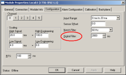
you might also want to tinker around with the setting shown below ...

but ... be careful ...

if you use this method to put enough "filtering" on the input signal to suit the operator's tastes – then you might be limiting your ability to control the process ...

specifically, a filter basically "slows down" the input signal's ability to reflect rapid changes ...

in some cases the ability to control the process might actually be improved by this effect ... in other cases your control over the process might be adversely affected ...

one size does not fit all ...

.

digital_filter.PNG
 
@ Ron thanks for your help once again, ill try out the timer suggestion, question with the timer suggestion though. You mentioned to based on a timers .dn bit to mov the raw scaled data to a "outbox" location, when you say "outbox" do you just mean another memory location that the raw scaled data is moved to? if so why is it called "outbox"??

So as an example say you raw scaled value came out to be 14.53(PSI) and set up the timer to trigger every second, now after 1 second a move will be initiated to the "outbox" but also keeping in mind that the raw scaled value may have changed during the duration of the timers delay, but that won't matter because we are only viewing data every time the timer's .dn is set, and i guess the timers .pre depends on how fast you want to see change. Nice i just had to write it out to understand what you meant (nice method btw). Just one last thing ron, their are most definitely other ways to do this, and as i have stated in the first post to filter using 0.9(which if i recall is called the weight) if you know that method please explain if you have time, its just killing me that i don't remember that method lol.
 
@ Mickey thanks, just one question though, as you know damping can have many definition, but for this aspect the smaller the number of the "C" constant the more damping, does that mean the smaller that number goes the more we would see the "FV" filtered value fluctuate??
 
when you say "outbox" do you just mean another memory location that the raw scaled data is moved to?

yes ...

if so why is it called "outbox"??

just my personal way of saying that it goes "out" to the HMI ... sort of like the "in basket" and the "out basket" that you'll see on many office desktops ... you could call it anything that makes sense to you ...


incidentally, some programmers call the method I mentioned earlier a "de-bouncer" rather than a "filter" ... based on what you've posted, I'd say that you really want to "de-bounce" the signal for the HMI - rather than "filter it" ...

if you have time ...

I'll help where I can – but I'm literally swamped with work right now ... I'm juggling cu$tomer work with the forum ... if I have to drop "something" guess which one it has to be? ...

good luck with your project ...
 
Last edited:
does that mean the smaller that number goes the more we would see the "FV" filtered value fluctuate??

No, the less it will fluctuate.

Try it and see for yourself, use a word for the constant value that you can change on the fly.
 
@ mickey these were my finding after conducting a simple test, What i did was i fist created a 2 timers one to add a value of 0.01 to the Unfiltered tag (UV), with a preset of 10000ms (this is to simulate an actual process) and another timer to pretty much compute how often we want the FV calculated, this i put at 1000ms. Then i had an ADD instruction to add a value of 0.01 to the UV value so every 10 seconds we add 0.01. So i gave the "C" constant value of 0.1 first, which was very little damping and even though the UV was changing every 10 seconds the FV didn't change as oftern, matter of fact their were 6 digits after the decimal place, and the last 2 digits are probably the ones that fluctuate. So then i kept increasing the "C" value 0.2,0.4,0.5 all the way to 0.99 and what i realized was the FV became more responsive such that it changes much quicker than than before alas the more damping the more it will fluctuate, i didn't give the "c" a value of 1 because you just stop damping at that value so "C" works up untill a value of 0.99 which you had stated. At least now i see how it works, and i thank you guess for that. If you have more additions to this topic please send them my way

Thanks both Ron & Mickey cheers :)
 
@ Bit Bucket 07

the formulat states

FV = FV+ C(UV + FV)

UV = unfiltered value

You mentioned that once FV is computed when the UV is decreasing that it will result in a negative value, but if the input value is decreasing and it is a positive value then by computing the math FV will never be negative, the FV will only turn negative if the input from the process actually becomes negative. You can try this by using what i mentioned in my post prior to this and instead of an ADD use a SUB, and see what happens
 
That's different from the formula in the attached text file.

FV=FV+C(NV-FV)

Where:
FV= Filtered value
C= constant (range 0-1) The smaller the number the more dampening.
NV= New Value

Filtered Value= Filtered Value+Constant*(New Value-Filtered Value)
New Value = Unfiltered Value
Constant= 0.00-1.00 The smaller the number the more damping.
 

Similar Topics

i have a laser sensor from AB that is measuring block height, it works great but problem i am having is the signal is just all over the place up...
Replies
11
Views
5,432
Hey, I've read some threats here about analog signal filtering. Most propose a first order filter. I've done some experiments with first order...
Replies
4
Views
6,004
Hi All, I would like to ask you if possible to have some samples code for the realization of a software filter to be used in a PLC Micrologix...
Replies
2
Views
2,048
Hi All, Please see my below logic and AI configuration for a new Sick Laser DT500 that I am using for position feedback. The compute instruction...
Replies
3
Views
2,056
Hi all, I'm trying to access the analog filtering wizard with my 216 CPU and EM235 but I can't seem to find it. Does anyone know if this is...
Replies
2
Views
2,365
Back
Top Bottom