Analog out to analog in on same plc

thierry2003

Member
Join Date
Oct 2003
Posts
70
I am trying out some basic analog stuff. For the ease of testing I am connecting the analog output to the analog input on the same plc.
However, it doesn't work.
I've checked my program over and over and cannot find a reason.
This made me thinking, is it possible to connect an analog out directly to an analog in?

BTW, both are 4-20 mA
 
Two things are often confused on 4-20 mA anaolg circuits. First is polarity - it seems intuitively wrong to wire + to + for example. Second is commons - most analog cards have common tied to the power supply common.

The details vary with brand and model. In general you should wire:
Power supply + to analog out common (+)
Analog output signal to analog input signal (+)
Analog input common (-) to power supply -
 
thierry2003 said:
This made me thinking, is it possible to connect an analog out directly to an analog in?

I've done it with voltage In/Out cards. But it should work with mA, too. The PLC shouldn't care where the signal comes from.

Maybe you need to verify that the output card is actually sending a signal and the input card is configured properly. Have you tried using a mA simulator and multimeter to isolate each card and verify that it is working as expected?

AK
 
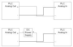
In your original post is sounds like you ran 2 wires from the Analog Out to your Analog In. Check to see if your Analog Out supplies the current, or controls it. A-B card control the current from a external DC power supply, see below:

pic 1.jpg
 
Analog IO Stuff

On some analog IO, the modules must be configured correctly via DIPS switches or jumpers. Sy/Max for instance, you have to remove a cover on the side of their modules to access jumpers.

Also, be aware that many makes of analog outputs require user power (usually 24VDC). Best to read installation chapter of module manual for wiring info.

Programming-wise, if we are talking TI, best to monitor register data. For instance, I was testing a 505-6208 Output wired directly to a 6108 Input (output 1 to input 1 through O8 to I8, relating directly to your question). I used PLC Workshop 505 to monitor via a Data Window where I entered the correct register addresses and changed the output values to monitor at the inputs (TI Soft can also do this). 20mA corresponds with 32,000. I found that the 6208 outputs all worked fine, but the 6108 had a bad input channel #4!

This stuff is a headache to have to figure out, but once mysteries are solved it is very cool to work with. Keep playing with it and find out what works best for you.

Jimmy Williams
 
Last edited:
I started to reply to this one .. but then I checked the date on the original thread ...


still, maybe someone out there is interested in the basic ideas ... if so, we need to start out by taking a closer look at the post by cnrservices (incidentally, we haven’t seen him around here since back in 2004) ...


but if the top sketch is supposed to be an Allen-Bradley system (example: 1746-NO4I output to 1746-NI4 input) then the polarity that has been shown is wrong ... specifically, these particular modules would require positive-to-positive and negative-to-negative connections to do what our original poster wanted to do ...


but then, maybe cnrservices had some other type of hardware in mind ... like I said, we need detailed information in order to give detailed answers ...


going further ... IF (big IF) we’re using the hardware that I mentioned above, then we’d also need to be aware of the differences in scaling between the input and the output modules ... specifically, we’d need to enter a value of 31208 into our output address to get a maximum current output of 20 mA ... and our input module would give us a reading of 16384 in response ... and ... we’d need to enter a value of 6242 into our output address to get a minimum current output of 4 mA ... and our input module would give us a reading of 3277 in response ... assuming of course that everything happened to be in perfect calibration ...


and I haven’t taken a really close look at the bottom sketch ... but enough to say that if it’s supposed to be Allen-Bradley, then it appears to be wrong also ...


note: the only reason that I checked the date was because of the BIGGGG picture format in cnrservices’ post ... I wondered “how did he get by the new 550 pixel limit?” ... answer: the limit didn’t apply on the old forum format ...
 

Similar Topics

Our company is building a new machine. Our mechanical eng. only gave me a 2 inch conduit across the machine. I need to run 115ac from the main...
Replies
15
Views
20,659
Why AMIo800 Analog input module's I/O LED is Lighting up Red? Checked module connections, 4-20ma wires etc but this light is continuously Lighting...
Replies
1
Views
62
Hello! Hope you are great. I need to make a change in a PLC with ladder logic. I will mount a analog valve and I need to control it in ramp up...
Replies
7
Views
269
Does anyone have experience wiring this type of analog pressure transmitter up? It's 4 wires. 3 blacks and 1 green which I assume is earth...
Replies
9
Views
240
I have a 170AAO92100 card that I am interested in using as a 10 volt output. Is there setup that I have to do in order to change output or simply...
Replies
0
Views
79
Back
Top Bottom