hickman,
I'm pretty sure that this will give you what you want.
(Update: I was pretty sure... then I noticed a problem. I will leave it as I originally designed it and then show what I found and how I handled it)
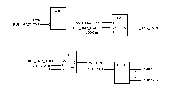
FIGURE-1:
Figure-1 shows the basic control for your Select Timer, the Select Counter and the Select Output.
As long as power is applied and the WAIT_TMR is not running then the SEL_TMR runs. When the SEL_TMR times out, the counter is incremented and the next motor is selected for check.
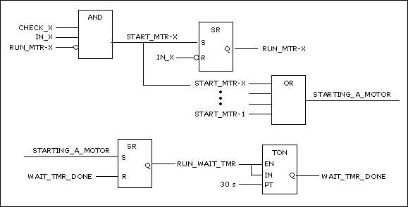
Figure-2 shows the control for starting a motor and running the WAIT_TMR.
When CHECK_X is activated, if IN_X is ON and RUN_MTR_X is OFF, then turn ON a signal called START_MTR_X. That signal is applied to the SR to run Motor_X.
FIGURE-2:
At the same time the signal is applied to a set of OR-Gates. All of the Start_Mtr signals are applied to this set of OR-Gates. Depending on how many inputs you are allowed to use, you might have to OR-the-OR's to get the final signal - STARTING_A_MOTOR.
The STARTING_A_MOTOR signal is applied to an SR which turns ON RUN_WAIT_TMR. This signal causes the WAIT_TMR to run and, at the same time, disables the SEL_TMR.
In Figure-2, as soon as RUN_MTR_X goes ON, then the output from the AND-Gate goes OFF. RUN_MTR_X will stay ON until IN_X goes OFF.
YIKES!!!
I just realized that I have created a highly likely "race condition" in Figure-2. That is just as well!
This allows me to give you a real example of a race condition (in answer to your question) and how to fix it.
A "race condition" exists if all necessary and expected subsequent results do not, or might not, occur before the causal factor is removed - simply because the casual factor is removed
too soon.
There are variations on that theme. Some race conditions prevent expected actions from happening while others cause unexpected actions. In any case, a race condition is a timing issue between cause and expected effect.
The "race condition" I see involves the following signals: START_MTR_X, RUN_MTR_X, STARTING_A_MOTOR, RUN_WAIT_TMR and WAIT_TMR_DONE.
The START_MTR_X signal is applied to the SR to produce the RUN_MTR_X signal. At the same time, the START_MTR_X signal is applied through the OR-Gate(s) to produce the STARTING_A_MOTOR signal. That signal is then applied to an SR to produce the RUN_WAIT_TMR signal.
Now... It takes a certain amount of time for a signal to propagate through the various devices.
START_MTR_X goes through one device to produce RUN_MTR_X.
START_MTR_X goes through at least two devices to produce RUN_WAIT_TMR.
It is very probable that RUN_MTR_X will go ON
before RUN_WAIT_TMR goes ON. When RUN_MTR_X goes ON, then the necessary conditions for START_MTR_X are no longer present - START_MTR_X will go OFF. It will, of course, take time to turn OFF START_MTR_X - because it takes time for a signal to propagate through a device.
If it happens to be that you are allowed to use a single OR-Gate with 12 inputs (not likely) then START_MTR_X has to go through only two devices to turn ON RUN_WAIT_TMR.
In the time it takes to turn ON the START_MTR_X signal and then turn it OFF, it just might be the case that START_MTR_X will have enough time to cause RUN_WAIT_TMR to be turned ON before START_MTR_X is turned OFF... maybe... it's a "race" to see who finishes first.
If you are not allowed to use 12 inputs on an OR-Gate then the START_MTR_X signal has to go through more than two devices to turn ON RUN_WAIT_TMR. This would pretty much guarantee that the casual factor would go away before all of the subsequent actions were produced - that is, START_MTR_X
will go OFF before RUN_WAIT_TMR is turned ON.
So... how is that situation handled?
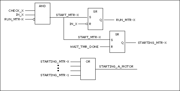
FIGURE-3:
Figure-3 shows my solution to the race condition. As soon as START_MTR_X goes ON, use that signal to SET "STARTING_MTR_X". This signal will be retained until RESET.
Then, instead of applying START_MTR_X to the OR-Gate(s), apply STARTING_MTR_X. The STARTING_MTR_X signal will remain ON until the WAIT_TMR_DONE goes ON.
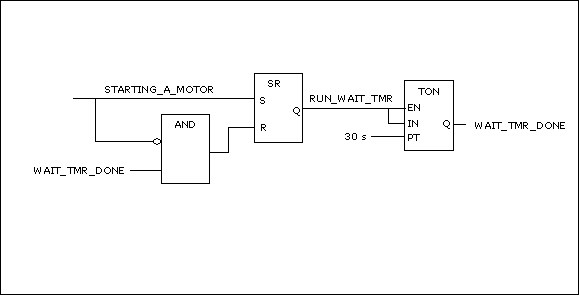
Then apply STARTING_A_MOTOR to the SR as shown in Figure-4.
FIGURE-4:
When STARTING_A_MTR goes ON, the input to the AND-Gate goes OFF and the output from the AND-Gate is turned OFF. This removes the signal from the RESET at the SR which provides RUN_WAIT_TMR. So, with the RESET signal removed and the SET signal asserted, the RUN_WAIT_TMR signal is turned ON.
BTW, In SR Latches, the R Input over-rides the S Input. That is, if both signals are ON then the output goes OFF.
The RUN_WAIT_TMR signal causes the WAIT_TMR to run. While RUN_WAIT_TMR is ON the SEL_TMR is disabled. When WAIT_TMR_DONE goes ON, STARTING_MTR_X goes OFF (START_MTR_X is long gone).
After a certain amount of time, STARTING_A_MTR goes OFF (it takes time for the conditions to propagate through the devices).
Since STARTING_A_MTR is OFF and WAIT_TMR_DONE is ON, the AND-Gate provides a signal to RESET the latch providing RUN_WAIT_TMR. The WAIT_TMR goes OFF and WAIT_TMR_DONE goes OFF.
When RUN_WAIT_TMR goes OFF the SEL_TMR is re-enabled. The process then moves on to check the next motor.
So... Figures -3 & -4 should provide the basis for a functional solution to your original question.
It should also answer your question about "race conditions"... I hope.
Regarding
NOT CHECK_X and NOT_CHECK_X, you are correct.
NOT CHECK_X is the Inverse of CHECK_X, as developed
at the input to the logic box (the "bubble").
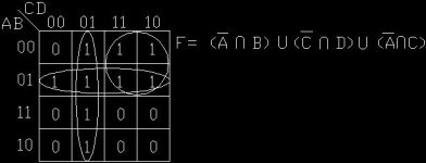
And, K-Map?
A K-Map (named after a guy named Karnaugh) is a method of simplifying combinatorial logic to a minimum number of gates. The smaller the system, the easier a K-Map is to use.
However, what many don't realize is that any system can be broken down into to smaller sub-systems which can then be subjected to the K-Map.
A K-Map can be made to manage mathematical routines. While it doesn't actually do any math, it can easily respond to, or call for, particular math operations in conjunction with field or internal conditions.
It is also a way to create a precise Sequential Control. If all conditions are accounted for, then the resulting code can be written in
any order and the logical operation will
always be correct. It can even account for unexpected failures in the field. As in all programming, it all depends on the amount of effort the programmer is willing to expend.
BTW, for the PLC Programmers,
These gates translate directly into ladder symbols and rung layout. An AND-Gate is simply two or more inputs in series. An OR-Gate is simply two or more inputs in parallel.
If the input to a particular gate has a "bubble" (a small letter "o") on the line at the input to the gate then that particular signal is subjected to "Examine if OFF". Otherwise the signal is subjected to "Examine if ON".
It really is pretty straight forward!


