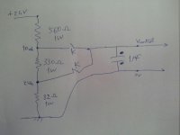
2 vdc and 10 vdc signals generate

Kataeb

Member
Join Date
Jan 2007
Location
www.livelovelebanon.com
Posts
632
i need to control a valve with analog input 2 to 10 vdc, without using any analog output device, because the control does not contain any automation.
to keep it simple, i am using relays which should switch on 2 vdc (valve off) or 10 vdc (valve on). so i am looking for a simple circuit to generate 2 vdc and 10 vdc signals.
 
Why use an expensive valve that has an analog positioner in the first place? But if that's what you've got, then a simple voltage divider using two potentiometers will work. Put legs 1 and 3 across your standard 24V DC and adjust until leg 2 gives you 2 or 10V. Then switch using relays. It's messy but should work ok. Size the pots so they have a couple mA flowing them but double check the wattage to make sure you don't have them running too hot.
 
I think you only need to sen 10V to open and 0V to close the Valve.

The 2VDC corresponds to the 4mA conversion into Voltage with the help of a resistor.
 
Any valve positioner that takes an analog input signal will have a 'fail-safe' setting that becomes active should the postioner detect that it has 'lost' the input signal.

That's one of the reasons a 'live-zero' signal like 4-20mA or 1-5Vdc or 2-10Vdc, where zero volts means an open circuit or loss of input signal, is so widely used in industrial controls.

This could be relevant should you decide to use 0V to close the valve, because 0V might 'fail-safe' as a fully open condition.
 
The 2V or the 4mA are relevant when you are reading the analog input and I agree with danw.

If you just want to close the valve (analog output), what is the difference sending 2V or 0V. If you send 0V you don't have to create a voltage divider.
If you send only 2V, the valve might not close completly!!
 
What type of valve and whats the application?

Depending on the above you could simply switch a 10 volt supply, but would highly recommend replacing coil with 24 volts DC type, if this is at all possible.
 
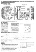
Base on user manual and your attachment you NOT need to use resistor,

if you check again the user manual the DIP Switch S7 & S8 provide if any

signal input fail the valve will fully closed if you configuration

S7 -OFF and S8-ON, this reflex to your relay Contact NO, Deactived the relay.

if the control no require RESET.

others option you can use 5V signal as signal input on DIP Switch S1 -OFF

and S2 -OFF for fully open via relay contact.

What you need the 24VDC supply convert to 5VDC using fix Voltage IC e.g. LM7805

Use 0.1AMP fuse on 24VDC incoming

only use 1 relay and NO

if your responbiltiy to take care the safety and asset.
 

Similar Topics

Intern here, I have been tasked with setting up a 24V Keyence vision system. Looking at the control prints, the existing input signals are sinking...
Replies
7
Views
1,808
I have been requested to test this proportioning valve for PLC control of flow/pressure. Dwyer Series SVP Proportioning Solenoid Valve The flow...
Replies
10
Views
408
We normally ground the -24VDC side of a control systems power supply. What are you folks thoughts about grounding the -24VDC side of a class 2...
Replies
1
Views
106
I have a conundrum with this current circuit. I have a Siemens 1215C AC/DC/Relay and an old drive - Ratiotrol (now Boston Gear company I...
Replies
7
Views
1,162
I have begun using 480VAC power supplies in my panels to keep heat from a transformer out of the panel. This works great if the panel is mounted...
Replies
17
Views
4,126
Back
Top Bottom