Diffrence between 24 VDC and 24VDC from a power loop from a DCS.

Join Date
Feb 2007
Location
Oklahoma
Posts
277
Hi to all. We have a pH transmitter from Mettler Toledo (M400) that can be powered by 120 VAC or 24VDC. We also have a transmitter (M420) that is powered by 24 VDC loop power. I was going to install a M400 as a temporary set up until we got another M420 in. I set up the M400 in the shop using a dc power supply set to 24 VDC. When I tried to hook it up in the field on the 24 VDC loop it would not come on. My DC meter was reading 24 VDC in the field on the loop power. To make a long story short, I am wondering what the difference between 24 VDC and 24 VDC from a power loop. The power loop also has the 4 – 20 mA imposed on it for the Hart function. The power loop is on our DCS. Any help to understand the difference would be greatly appreciated. :confused:
 
Thank you Mickey for your help. I was wondering why a device that is powerd by 24VDC workes on a power supply but will not work on 24VDC power loop. I thought 24 VDC was the same?
 
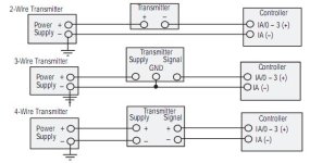
MM, the 24vdc loop is designed to use 0-<4ma as the power available to energise the device, then the remaining 4-20ma is the input current to the analogue plc input. So depending on the supply load of the 4 wire transmitter, you would overload/possible burn out the analogue card.
It is a 24vdc supply as such, but not to run other devices. You could swing the wires over to the 24vdc DCS power supply to run the 4 wire Transmitter, but you wouldn't have any wires for the analogue signal back to the PLC input.
 
The 24Vdc supplied for loop current on a DCS is frequently part of an analog input circuit on a DCS, where it is not a 'stand alone' power supply, like the one you used in the shop.

It isn't clear exactly what part of the M400 4 wire analyzer that you connected to, whether it was the 4-20MA output terminals or the power supply terminals.

If you connected the M400 4 wire analyzer's 4-20mA output terminals to the loop (in between the power supply and the DCS analog input), then there was no power on the M400 to drive the sensor or the analyzer's microprocessor and its logic. Without power, the M400 won't turn on.

If you connected the M400 4 wire analyzer's power supply terminals to the loop power connections (in between the power supply and the DCS analog input), then the unit attempted to pull some current up to its rating of 0.42A (420mA) through a circuit designed to carry a maximum of 22mA.

The electrical spec for the M400 analyzer is 20 to 30Vdc 10VA. 10VA at 24Vdc is 0.42A or 420mA

However the DCS controller's analog input typically has a 250 ohms shunt resistor across its inputs and that resistor is in series with the DC power supply. The resistor would drop a significant portion of the voltage in the loop, probably to the point of limiting the power to the point where the unit would not turn on. Depending on what the current draw was and how long it was connected, the analog input resistor might have burned out.
 
Thank you PLCnovice61 and danw for helping. Dan I was connecting the two wires to the power supply terminals on the M400. After reading your post, it looks like the M400 was needing 420 mA which I was getting from the power supply in the shop. The wires in the field from the DCS loop only had 22 mA, which was not enough current to run the M400. What I have learned from this is to always make sure there is enough current to run a device. If you could please let me know if I am understanding this right? Again , thank you all for your help.
 
I can't make a determinative statements concerning DC power from a DCS because DCS documentation is not public. You have access to it, I don't. In the PLC and analog I/O world, DC power for analog inputs is a vendor-to-vendor situation and I suspect that's the case for DCS as well.

You need to check the DCS documentation to determine exactly what DC power is provided and whether the analog inputs common/return/(-) is hardwired back to the power supply return/common/(-). If the analog input (-) is hard wired into the circuit for loop powered instruments, then the DC power is not usuable for the M400 purposes. Having the analog input resistor in the power circuit is just not viable for power for the M400. In that case, the M400 would require an independent power supply.

If you need to procure an independent 24Vdc power supply, get one rated higher than the required power.

A 600mA supply is rated 15 watts, a full 1 amp supply is 25 watts at a typical $20-25 premium.
 
I did find a M420 that worked good on the loop power. I just wanted to understand how loop power works. I do find it very interesting that a meter can read can read 24 VDC from positive to negative wire, but one has to check how the circuit is set up. Everyone has been of great help. Thank you all so much. Have a great day.
 
Last edited:

Similar Topics

Hi, We have a machine that we wan't to restart after power on if the emergency stop is OK. But if the emergency stop is tripped with the button...
Replies
21
Views
6,449
For an automation project we need to program for the first time in TwinCAT (V2). The Twincat software and PLC control is new to me. Programming in...
Replies
7
Views
5,101
how to differentiate between rotary and linear motion exactly?any example about these two motion? i am starting working on packaging and tube...
Replies
1
Views
1,917
I 'd like to know if force is different in s7-300 and 400 because I saw an article that said they are diiffrent but didn't explain about it
Replies
9
Views
3,497
Hi. First of all, sorry for my lack of some basic knowledge. Actually, I have worked with AB SLCs and never worked with DCS. That is the...
Replies
12
Views
8,915
Back
Top Bottom