Shackle Bender Help

Join Date
Sep 2018
Location
Chattanooga
Posts
68
We have a shackle bender that has a ML1200 that was programmed from an outside contractor. Problem is we are in the middle of commissioning the equipment and we are having to do alot of stops in the middle of the process and restart. The programmer didnt account for this so we have to go through and flip all the limit switches for the PLC to think it has completed the process and it will restart the process. WHat would be the best way to use the Run/Setup switch to restart the process? The programmer used alot of latches, unlatches, and ONS's. That equipment runs fine unless you have to stop in the middle.

I've included the program in a compressed file. To me the program is very scattered and not organized. Hopefully someone can make heads or tail. I'm not asking for anyone to do my job for me but maybe just point me in the right direction.
 
I'll take a look later, but I would be calling the programmer and having him fix this. I would not consider this a small oversight in this situation and they need to address it.
 
Yeah, that's a little messy. It looks like a simple-enough process that you should be able to sit down with pencil and paper and write out a "discrete state machine" with each step in the automatic cycle, then write a program that causes an Index register to increase each time a step is complete.

But first, the reset matter. There look like six Latch bits in the program (B3:0/1,2,4,5,8 and B3:3/15).

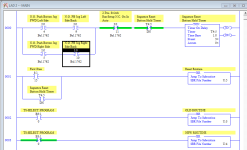
I sometimes like to use buttons in combination to perform a reset of the program. In your program, it looks like the Left and Right jog In/Out pushbuttons only work when you're in AUTO mode, so you could use them in conjunction with the "Setup" mode to perform a program reset.

Here's my suggestion: Create a Subroutine with nothing but OTU instructions to unlatch the bits you want unlatched. Looks like Bit B3:0/1 should be latched True with an OTL, rather than false with an OTU, on startup.

Then call that Subroutine after both the Jog FWD and Jog BACK buttons for either side of the machine are pressed and held for 3 second while the Auto/Setup switch is switched to Setup.

Reset_Routine.PNG
 
Last edited:
Just about the worst scenario for someone else to go in and fix it. Sparkie is absolutely correct, get the original programmer involved.

I will definitely consider that but I am trying to use this as a learning experience as well. I’ve been trying to learn how to program over the last few months so every chance I get I want to use it to my advantage.
 
Yeah, that's a little messy. It looks like a simple-enough process that you should be able to sit down with pencil and paper and write out a "discrete state machine" with each step in the automatic cycle, then write a program that causes an Index register to increase each time a step is complete.

But first, the reset matter. There look like six Latch bits in the program (B3:0/1,2,4,5,8 and B3:3/15).

I sometimes like to use buttons in combination to perform a reset of the program. In your program, it looks like the Left and Right jog In/Out pushbuttons only work when you're in AUTO mode, so you could use them in conjunction with the "Setup" mode to perform a program reset.

Here's my suggestion: Create a Subroutine with nothing but OTU instructions to unlatch the bits you want unlatched. Looks like Bit B3:0/1 should be latched True with an OTL, rather than false with an OTU, on startup.

Then call that Subroutine after both the Jog FWD and Jog BACK buttons for either side of the machine are pressed and held for 3 second while the Auto/Setup switch is switched to Setup.

Thank you for the advise. The left and right jog buttons ONLY work on SETUP. I don’t see that would alter your advise at all but I wanted to make you aware in case you wanted to change it.
 
Hmm.... maybe you can't use pushbuttons for this, then. I must have misunderstood the "On in Auto" label.

The MicroLogix 1200 does have a physical Run/Prog toggle switch, so you could remove the timer and the pushbuttons and only execute the Reset JSR when S:1/15 is true (which is for one scan when you enter Run mode).

Think about how you would reset this machine if something got jammed or out of sequence; would you jog two cylinders in the reverse direction until they both made their full-retract sensors ?

If so, then holding the "jog reverse" buttons for a couple seconds after the cylinders have made those sensor could be your "secret reset command".

I don't know your machine or its elements, so you always need to make your own decisions and review any advice you get from anonymous people on the Internet.

I should probably also try to do better to stay anonymous...
 
It seems to me that if you are in set-up mode you should be able to reset all of the states for auto mode since, well, you aren't in auto mode. Then again, I tend to look at things a bit simplistically sometimes.

Keith
 
Reading through the program, I think this is the order of operations in the machine cycle:

0 E-stop or Power-Up
10 Ready To Cycle
20 Foot Switch Activated
30 Part Rest Up
40 Push Main Cylinders Forward
50 Hold Main Cylinders Forward Position
60 Part Rest Down
70 Pin Strip Solenoids ON
80 Pin Strip Solenoids OFF
90 Retract Main Cylinders
100 Cycle Complete


Each transition between steps can be essentially "If at StepIndexValue = X, and conditions 1,2,3 are true, then move X+10 into StepIndexValue"

This also lets you program alarm/jam logic, like "if in Step 40 for 10 seconds but Left Cylinder Forward LS not made, then declare a jam or failed sensor on Left Cylinder Forward". That's about the time you discover there are a couple dozen potential sensor, valve, or mechanism failures that you would like the PLC to detect and announce, and that you're going to really want a small HMI, or at least a lengthy list of "this many flashes of the Ready lamp indicates a fault code" iterations.
 
So the bender will take a shackle that’s already bent into a U shape and create the inset bends where the bolt slides through and threads into the eye.

During “setup” you can jog the left and right cylinders in and out that are monitored by a set of limits each. Each main cylinder has a “parts stripper” limit switch as well. It essentially is a separate solenoid for a a separate cylinder on the main cylinder. It will keep the die in place while the main cylinder retracts. When the limit is made then it will retract essentially stripping the part out of the die. In run, when the foot pedal is activated the first time the solenoid controlled parts rest raises into line with the main cylinders. On second activation the main cylinders fire and the process begins. One process will run appx 20 seconds. The parts rest has a limit that is made in the down position.
 
At what step does the Part Rest drop ?

Does the Part Rest go up and down every cycle, meaning that you have to tap the foot pedal twice per cycle ?

Does the operator tap the foot pedal and release it, or hold it down ?

Are there any safety devices installed (or necessary) on this machine, that might be used to also drop out of Automatic mode ?
 
It seems to me that if you are in set-up mode you should be able to reset all of the states for auto mode since, well, you aren't in auto mode. Then again, I tend to look at things a bit simplistically sometimes.

Keith

Yes that would work on the main cylinder limits but the part stripper limits have to be actuated by hand because they have no manual/jog control.
 
At what step does the Part Rest drop ? part rest drops when the main cylinders make the forward limit switches
Does the Part Rest go up and down every cycle, meaning that you have to tap the foot pedal twice per cycle ? yes

Does the operator tap the foot pedal and release it, or hold it down ? A tap is all that was asked for from what I understand

Are there any safety devices installed (or necessary) on this machine, that might be used to also drop out of Automatic mode ?Not at this time

Currently the Estop is wired in series with the line voltage for the PLC. However, now that I think about it it may be better practice to have the Estop reset the cylinders in case of a pinch injury. I could just an XIC in parallel with the first pass bit and the Timer down bit in your example above?
 
Last edited:
Could on I just not get rid of all the latches and unlatches and replace them with their own hold in in parallel with its input? From everything ive learned thus far OTL's and OTU's have always been a last ditch effort kind of thing.
 
Last edited:
A bunch of seal-in logic is not a whole lot better than a bunch of latches and un-latches. Latches are perfectly fine logic for some purposes.


I would personally do it as a state machine, where N7:0 is the Step Number.

Individual actions or events can only happen during their step number.


0 E-stop or Power-Up

> Auto mode and all cylinders are in appropriate locations
10 Ready To Cycle

> Foot Switch Tap
20 Part Rest Raise

> Timer to allow part rest to rise
30 Part Rest In Up Position

> Foot Switch Tap
40 Push Main Cylinders Forward

> Cylinders reach forward LS
60 Part Rest Drop

> Part Rest reaches LS
70 Hold Main Cylinders Forward Position

> Hold Cylinders Time Expires
80 Pin Strip Solenoids ON

> Short Time Delay
90 Retract Main Cylinders

> Main Cylinders reach retracted LS
100 Pin Strip Solenoids OFF

> Short Time Delay
0 Initialized
 

Similar Topics

I have 16 cb_E connected to OP16 via fiedbus and the cb-E connected to l60 controllogix via en2t ethernet. using generic module in IO config so I...
Replies
2
Views
1,715
Hi All, I'm setting up a Brabender feeder via Ethernet I/p, I have the start and stop figured out but the int to real has me up against the wall...
Replies
2
Views
2,813
I have a client who purchased a sheet metal bending machine from a company called IMS-Powerfold about 16 years ago. It looks to me like the...
Replies
24
Views
12,096
All, I have a customer that wants me to message between a SLC 5/05 processor and a Brabender Congrav RC4 using a DL-4000. Do I use the SLC...
Replies
1
Views
4,878
Hi, We have an application that has a device that goes through a reboot (appears un-graceful) What then happens is the MVI module appears to hang...
Replies
0
Views
49
Back
Top Bottom