Communication problem between panelview 800 to compactlogix l2 controller

erivinoth

Member
Join Date
Jun 2011
Location
pondy
Posts
29
Hi experts,

I have Panelview 800 Teriminal (version 4.012) connected to 5370 compactlogix L2 controller(1769-L24ER-QBFC1B). Through Ethernet cable (2711P-CBL-EX04).
I am using Connected Component workbench version 10.01. i create an application START, STOP, PUMP OUTPUT. I map the tags from Logix designer 5000 and validate. There is no error but warning only (attached). And downloaded successfully. Then i try to start from HMI its not working. (No changes in the HMI and Ladder Program).

Then i found in the PLC indicator (NS) is still blinking (Green) while connected with Panelview 800 Terminal. But when i connected with computer to plc (NS) indicator will be stable (Green).
I read the manual It shows "Flashing green = The port has an IP address, but no CIP connections are established." I don't know what i have to do.

Kindly give me the solution.


Regards,

M.Vinothkumar
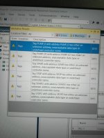
IMG_20170706_144103.jpg IMG_20170706_151847.jpg
 

Attachments

  • tag.xls
    33.5 KB · Views: 84
Last edited:
Hi,

PanelView 800 firmware revision 4.012 was recently released to allow, among other things, support for the CompactLogix 5370 L2 and L3 controllers. So your L2 controller should be fully supported using this terminal firmware revision.

Looking at the spreadsheet for your PanelView 800 tags, I can derive that there appears to be a few things that need to be "addressed", if you'll pardon the pun...

It looks like you have manually mapped the controller tags in CCW, while simply entering the controller tag names again under the "Controller" field in the Tag Editor. The "Controller" field, in the CCW Tag Editor, should contain the specific name of the controller shortcut you define under the CCW project's Communications setup.

If you have not defined your controller shortcut in the CCW project...

If you double-click on your PanelView 800 instance under the Project Organizer, you will open the Settings tab. This contains all the settings for the project. Under Communications you will see the Protocol selection.

Choose...

Ethernet | Allen-Bradley CompactLogix

You will then see the controller "Name" and "Type" field entries below. You can leave the default controller name "PLC-1" or you can change it to something more meaningful, if you wish.

Next you enter the IP address that the CompactLogix controller is currently assigned to use. This is important - you must also append the correct path syntax to the end of the IP address that you enter...

Example:

192.168.1.50,1,0 <<<correctly defined path

That should be the controller shortcut defined and ready to use with the Tag Editor...

Go to the Tag Editor>External tab in CCW and check the following...

The "Tag Name" field represents the name of the terminal tags you use in the CCW project. You can name these the same as the controller tags they are mapped to, or you can assign them different names of your choosing.

For all of your particular controller BOOL tags, the "Data Type" field should be set for "Boolean" and not "16-Bit Integer", as your spreadsheet suggests you have selected. You do understand the difference here, yes?

The "Address" field should match the exact tag name for your tags in the controller. But do note - if you are mapping directly to Controller Tags then the raw Controller Tag name must be used. If your Controller Tags have Descriptions assigned, which may read as though they are tag names; you cannot use these as they are not tag references, but merely descriptors.

If you create Alias, Buffer, or Mapped Tags for your raw Controller Tags, then you can use their tag names instead. So, if you are simply mapping to the raw Controller Tags then their raw tag names need to be entered into the "Address" fields...

Example:

Local:I:1.Data.0

OR

Local:1:O.Data.0

And now the important part...

Under the "Controller" field you should now have a drop-down selection available with the name of the controller shortcut you defined back in the Communications settings. Selecting this will point the terminal's mapped tags to the correct device path. If you originally did not have any controller shortcut defined, then there would have been no selection available here. As you did not know what to enter, you appear to have just entered the Controller Tag names again.

Without a valid shortcut path defined, and with incorrect entries in the Tag Editor fields, your communications would never be established at runtime, hence the flashing NS LED indicator.

These are the basics in CCW for good controller communications setup. Once you've done a couple you'll quickly get the hang of it and it'll soon be second nature to you.

EDIT: I forgot to comment on the direct use of Controller I/O Tags in terminal applications but I'm more thinking let's get "something" basic working first before advancing you on to certain better practices.

Regards,
George
 
Last edited:
Hi George,

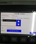
First of all i say Thanks, Based on your instruction i select controller and enter the ip address like 192.188.152.110,1,0. And Tag editor i followed you in Tag name like "LOCAL:1:I.DATA.0" in data type "BOOLEAN" in Address "LOCAL:1:I.DATA.0" in ACCESS field "READ/WRITE".
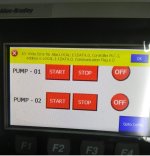
Then i downloaded this application to Terminal successfully downloaded. Then RUN the application. It shows error (Attached). I read the manual it shows "Write Error for Alias /*S:0 Param2*/, Controller /*S:0 Param3*/, Address is /*S:0 Param4*/, Communication Flag is /*S:0 Param1*/"

Corrective action mentioned below

Verify you have good communication to the controller.
Verify that the communication network cable is connected.
If new ladder logic is downloading to the controller, you could see this message. After the download, communication should run normally.
If a remote device not responding alert is present, then all external tags being written to will generate this alert.
Is the address configured in the controller? If the address is configured as read only at the controller, this address can not be written to. Set this external tag as read and remove panel devices from your application that can write data to this external tag.

everything i checked all are ok.
But still same condition no communication between PLC to HMI. PLC indicator (NS) is still blinking (Green).
Please look all sheets in Excel Report .

Can i update the firmware version to 4.014?

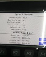
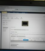
Notice: Please look the setting page for CCW Graphic Terminal version is:4.011 mentioned. But in Terminal "System information shows version is 4.012".

1.jpg 2.jpg 3.jpg 4.jpg
 

Attachments

  • T1.xls
    68.5 KB · Views: 57
Last edited:
Hi erivinoth,

Sorry for the delay in getting back to you.

Let's rule out some more basics here...

Have you configured the PanelView 800 terminal's Ethernet port settings?
This can be done on the terminal itself using the configuration screen.

I see you have a "Goto Config" button on your screen.
Click that and navigate to...

Terminal Settings>Communication

What are the settings?...

IP Mode = ?

IP Address = ?

Subnet Mask = ?

Regards,
George
 
Hi Geroge,

Thanks, i found the problem the terminal ip address was 169.254.170.100. But controller ip address is 192.188.152.110. Then i changed the terminal ip address is 192.188.152.112. Now it is communicating good.

Then one more doubt i want assign Timer values from Panelview. how to configure tags in both controller and Hmi.
 
erivinoth said:
...the terminal ip address was 169.254.170.100. But controller ip address is 192.188.152.110. Then i changed the terminal ip address is 192.188.152.112. Now it is communicating good...

That's good news. So it was that the terminal IP address was not in the same IP range as the controller. That "169.254.170.100" address that the terminal was using is known as an APIPA (Automatic Private IP Address). The terminal is default DHCP enabled which means that it will attempt to retrieve its IP settings automatically from a DHCP Server. When the terminal is connected to a computer, or the like, it will attempt to retrieve a DHCP address. If the computer is not running a DHCP Server, which is often the case, then it will time out looking for a DHCP address and Windows will automatically assign it an APIPA, such as the "169.254.170.100" address you found. APIPA addresses are in the range of 169.254.0.1 to 169.254.255.254. They give a device some limited connectivity, but are not really to be used for proper and permanent communications.

Anyway, moving on...

erivinoth said:
...i want assign Timer values from Panelview. how to configure tags in both controller and Hmi.

First, the controller tags...

In your controller, under Controller Tags, you can create a new tag and call it whatever you would like your Timer to be called. Let's say "Test_Timer". For this tag's "Data Type" choose from the list or type in "TIMER". This will automatically make the new tag a structured TIMER data type, which will include the following atomic data types...

[-]TestTimer
_[+]TestTimer.PRE <<<Timer Preset Value (32-bit integer)
_[+]TestTimer.ACC <<<Timer Accumulated Value (32-bit integer)
_[+]TestTimer.EN <<<Enabled Bit (Boolean)
_[+]TestTimer.TT <<<Timer Timing Bit (Boolean)
_[+]TestTimer.DN <<<Timer Done Bit (Boolean)

Now the PanelView 800 tags...

Note: For the PanelView 800 the TIMER data type itself cannot be assigned as a tag data type, but a TIMER's atomic data types may be assigned, such as the .PRE, .DN data types.

If you want to change, for instance, the timer's Preset Value from the PanelView then the controller's "TestTimer.PRE" atomic data type tag address is what you would use in the Tag Editor in CCW. Create a new tag...

Example:

Tag Name: TestTimer_Preset
Data Type: 32 bit integer
Address: TestTimer.PRE
Controller: PLC-1

Then use a Numeric Entry object on your screen and assign the tag "TestTimer_Preset".

Hopefully that achieves your goal for you?

Regards,
George
 

Similar Topics

problem in communication between micrologix 1200 & Panel View 600 Plus by serial DF1 Hello Friends i have to do communication between micrologix...
Replies
6
Views
6,604
I need some help. I have established communication between the Modicon Premium PLC, using PL7 Pro ver 4.5 software and Adam 6251 remote I/O...
Replies
4
Views
3,813
This Problem happened many times, is it only because the wrong type DB10Q0 should be DB1010 or any other possible cause? HMI log file ...
Replies
6
Views
8,541
Hello, I got 2 S7-200 communicating with each other and a computer with Simatic Softnet Lean 2006 communicating with both PLC. When...
Replies
1
Views
1,440
Hi i m using the S7-1200 plc while i want to commuinate plc to 3 Pc using Rj45 with LAN card, is it O.k ? or we can use other software woith hard...
Replies
1
Views
1,696
Back
Top Bottom