Simple Distributed I/O Assignment for PLC Students

Jieve

Member
Join Date
Feb 2012
Location
USA
Posts
274
Hello everyone,

Question for you all: I’m working on an assignment for my future PLC students and need a realistic example system from industry. They will be wiring up Siemens S7-300 CPUs with a single 16 DI/DO module, then connecting this via Profinet to a Siemens ET200S IM-151 PN, with one digital input module and one digital output module. They will have 2 pushbuttons with LEDs, one to be wired into an input and output to the ET200S and one to the wired to an input and output on the DI/DO module of the S7-300. They will have already covered timers and counters, so I’m looking for an interesting sample system and assignment to give them. My initial thought was a pump driven by two pushbuttons, one on the main control cabinet and one on the machine itself. Then, maybe there’s a delay of 5 seconds or something before the pump switches off after the button (toggle) has been pressed to switch it off. We have enough 24V contactors for them to wire up 1 each also as part of the system, so this could be thrown in there too. I was thinking the LEDs would represent the pump, but they could represent something else altogether. In fact the system doesn’t have to have anything to do with a pump. Maybe one of the contacts from the contactor could be monitored and turn on an error bit if it is not properly energized. Just some ideas of the top of my head. I would like to introduce a common programming technique/condition that is often necessary for real systems.

Does anyone have an idea of a realistic example from a simple system that you may have worked on/programmed that I could use as an assignment? Would be very much appreciated.
 
Will you be covering indirect addressing ?

How many hours will the students spend on the assignment?
 
Last edited:
Indirect addressing will have already been covered.

It'll most likely be 1 week to complete the assignment, but 2 weeks if it's necessary to take more time to cover the material.
 
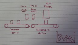
Two conveyor system.
Boxes are placed on conveyor 1 with spaces between them. The boxes are fed from conveyor 1 to conveyor 2 one at a time. When a box is detected on Conveyor 2, conveyor 2 runs for 5 seconds to position the box under a printer. The conveyor stops and the printer is energised for 3 seconds. Conveyor 2 then runs for 6 seconds to run the box off the end of the conveyor into a bin.

The pushbuttons are used as if they are the photo eyes.
The two LED outputs run each of the conveyors.
The contactor energises the printer.

The addresses of all the I/O is contained in a configuration DB along with all timer values.

ccc.JPG
 
L D, thanks a lot for the reply.

Actually, the assignment before this is going to be a real 2 conveyor system, somewhat similar to what you described (i posted about hardware for that system here in the past). That system is controlled by an S7-1200, possibly with the same model ET200S, but I didn't want to go to deep into the distributed I/O hardware since that lesson assignment will already be covering a lot of material.

The idea for this assignment was just covering the S7-300 and ET200S in detail, as well as assembly. I also wanted a somewhat intermediate level but not long assignment to give them, since from that point on we will be programming mostly just 300's and the programming will get a bit more intense.

During the lesson I want them to imagine that they are building this hardware setup for a real system. They will then program that real system. However, the "ACTUAL" real system in this case is a couple pushbuttons and LEDs. Any other ideas for a simple, hypothetical real system, just using digital I/O, counters and timers, not conveyor related?
 
Back door? - certain sequence of pressing switches enables contactor. LEDs indicate back door enable progress.
 
The passenger lift (elevator) is a classic classroom assignment, and highly scalable.

It lends itself to range from simple (2-floor) for the not so good students, to n-floor for the more experienced.

And if the high-flyers get ****y - get them to optimise the lift so that it will stop at a floor that someone has pressed the call button, but only if the lift is traveling the right way !.

Add the scenario, for example, an office-block lift - between 0800 and 0900 hours the lift should return to the ground floor automatically after it has been "used", ready for the next employees arriving for work.

Let the lift "learn" the most popular calling floors at any time of the day, program it to be there when not otherwise employed.

Go green and turn off the main lights in the lift cabin 30 seconds after the door closes if no destination floor is selected.

So many possibilities with lift controls, and the good thing is gets people thinking about a real application that they have all experienced.
 
Thanks guys for the responses.

daba, actually we have a PLC controlled elevator system for another assignment a bit later on, it was built by one of our interns a while back. Two elevators, 6 floors each, single controls at each floor ;) very cool project, I really like the modifications you mentioned too, will definitely save this thread for that.

L D I like the security door idea, lots of modifications I can do there as well, with button combinations, timeouts, etc.
 
It's not at all a real application (and may be a real head-scratcher for some students), but one of the demos used in the AB-TIA fast track seminar I attended was a sort of "Simon says". Four buttons, each with an LED. The user presses the buttons in whatever sequence they want, holding them for different periods of time with differing periods between pushes. When a fifth button is pushed, the LEDs repeat back the sequence.

And no, we did not code it ourselves. It was only a 3-day seminar and was mostly about using the software, not much actual programming.
 
One that I have used is a two pump control system with lead/lag pumps. The thing that I like about it is that it can be easily scaled for the appropriate complexity. Some ideas;

Switch selectable on which pump leads/lags.
Add an alternator so that the pumps alternate each start.
Add a high level start that starts the standby pump
Add a high/low level latching/non latching alarm.
Add control valves that open/close when appropriate.
Add different trips low flow, high discharge pressure etc.
Use a counter to keep track of the # of pump starts for service.


We deal with a lot of pump stations so these are realistic scenarios that we deal with on a daily basis.
 

Similar Topics

Hello again..trying something on an existing poorly written program and just wanted to double check something system is an A-B MicroLogix 1200 In...
Replies
5
Views
123
Hi all, Writng a FB in ST on Beckhoff TC for a pulser which turns on and off on a cycle, is paused by turning bControlInput to FALSE, but resumes...
Replies
6
Views
247
I'm trying to build my Classic Step 7 programming skills this weekend. I get stuck on little things that are not covered in YouTube tutorials. I'm...
Replies
7
Views
314
I have a program that does a 7 second "scan" sensor calibration routine whenever a setting (setting is called assistance level or "AL" and ranges...
Replies
3
Views
211
Hi all, I have a simple question that I have overcomplicated and gotten stuck on. I have a variable, we can call it "light" that I need to stay...
Replies
4
Views
305
Back
Top Bottom