You are using an out of date browser. It may not display this or other websites correctly.
You should upgrade or use an alternative browser.
You should upgrade or use an alternative browser.
Logix 5000 PID with slow process response and odd behavior
- Thread starter defcon.klaxon
- Start date
drbitboy
Lifetime Supporting Member
ΔCV = k∙Error executed at Δt intervals
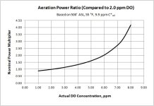
The non-linearity is vs. temperature, but more importantly vs. actual DO concentration. C* is the saturation concentration, which varies with temperature.
Nice. Does that assume the incoming DO is 0, or near 0? Or does the incoming DO really not matter because the issue is how close you want to get to saturation (driving force divided by (saturation - target DO))?
Last edited:
Tom Jenkins
Lifetime Supporting Member
Nice. Does that assume the incoming DO is 0, or near 0? Or does the incoming DO really not matter because the issue is how close you want to get to saturation (driving force divided by (saturation - target DO))?
The influent DO concentration is of some concern in rain events where the influent may be high in DO and consist mostly of groundwater.
Because of the oxygen demand exerted by the microorganisms as they metabolize the pollutants, the DO drops unless the oxygen supplied by the aerators is sufficient to maintain the desired concentration. The biological process will work at a variety of DO concentrations in the mixed liquor. However, if the DO is too low undesirable microorganisms will develop, and if it is too high energy is wasted with no process benefit. The desired DO concentration may be different for each plant, but 2.0 mg/l is a common default setpoint. Saturation is about 9.0 mg/l.
Tom Jenkins
Lifetime Supporting Member
I'm a bit late to this party, and the two resident PID geeks have already chewed the fat on this one, but for future DO control applications I'd personally suggest looking at what is called "floating point control". Tom Jenkins covers it very well in his book on Aeration control system design.
Thanks for the support!
drbitboy
Lifetime Supporting Member
Thanks for the support!
Is it really
- ΔCV = k∙Error, executed at Δt intervals,
Or is it rather
- ΔCV = k, executed at Δt intervals?
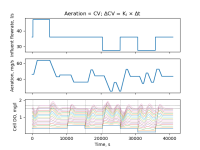
The top plot shows that algorithm exactly. The horizontal dotted lines are the dead band limits; the vertical dotted lines mark the times of the disturbances, basically one every 5120s ~ 1.4h. The only disturbance that was not recovered from before the next was the one at 20480s, with a simultaneous
- increase in influent DO, and
- decrease in flowrate,
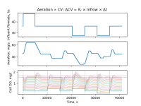
The bottom plot show a similar algorithm, but the change in CV at each update time is proportional to the inflow. The result are similar, but all cases returned to steady state before the next disturbance.
Last edited:
Peter Nachtwey
Member
drbitboy DMD. What about the dead time? You graphs do not show any dead time.
I can compensate for that with a Smith Predictor. It requires a circular queue or fifo.
The floating control works if the conditions don't change quickly but if one is capable of mathemagic, they can do so much better.
Floating control uses very slow rates of change to keep from over compensating. The CV will tend to oscillate between the upper and lower limits of the dead band.
Compensating for the non-linear response is not a problem either as long as you know how it is non-linear.
The advantage of floating control is that is is simple but it lacks when it comes to precision.
Perhaps the application doesn't need precision but the geek in me tells me I can model the system and compensate for the dead time and eliminate the dead band by using filtering such that the noise is lower than the dead band.
drbitboy
Lifetime Supporting Member
drbitboy DMD. What about the dead time? You graphs do not show any dead time.
Umm, I don't know what you are talking about. Maybe you are confused about the system: there is no dead time - or at least there is an immediate effect - in the system response to either changes in aeration or changes in flowrate; the dead time comes in mainly with the response to influent DO levels.
We can debate about how accurately my models represent the real system, because I chose to ignore several effects, but actually, no, there is no doubt that my graphs do show deadtime:
The first image below from the PDF I attached a dozen posts ago; the dead time in the effluent DO (top magenta line, bottom [Cell DO] figure in the top image) response to a change in the influent DO (bottom blue line, bottom figure) is obvious in the green-highlighted area.
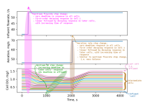
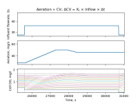
The second image below, from the floating-point control simulations, shows a response to simultaneous changes to both influent DO (bottom blue line in bottom [Cell DO] figure in the bottom image) and influent flowrate (top figure). The modeled effluent DO (top magenta line, bottom figure) starts dropping immediately (at Time = 25600s), though slowly, from the increase in flowrate, to which the control starts responding, and then at about 26600s, i.e. one dead time later, there is a second sharper drop as the decrease in influent DO reaches the effluent cell.
drbitboy
Lifetime Supporting Member
Floating control uses very slow rates of change to keep from over compensating. The CV will tend to oscillate between the upper and lower limits of the dead band.
This is for a waste water system with a dead time of around a quarter of an hour. Unless this is part of an industrial plant, typically the main disturbances are the numbers of showers taken and toilets flushed every morning. @Tom Jenkins can enlighten us some more, but beyond that, I suspect nobody gives ... well, nobody cares about fine control, and limiting the excursions and recovering to getting back to deadband in an hour or less is more than adequate.
If fine control was important, then the design would have a third DO sensor on the influent, so the aeration control could be feedforward with feedback trim.
As far as bouncing between deadband limits goes, we can see that is not usually an issue with Tom's floating control approach if the tuning is not aggressive, and there are simple strategies to improve on that:
- as Tom suggested, watch the slope of the PV and skip an increment when it is returning toward the dead band after an excursion
- I think that counting the number of increments applied to the CV while the PV is outside the deadband, and then "giving" some fraction (half?) of those increment back once the PV is again inside the deadband, would also work.
That said, the courts are open and my model is available: feel free to implement a Smith Predictor or any other control scheme on it. I'll add my floating control script to the repo on Github so you can see where to do it. [Update: done; do_jenkins.py]
Last edited:
Tom Jenkins
Lifetime Supporting Member
DrBitboy: If I'm controlling a VFD it is usually ΔCV = k ∙error. This is technically integral or proportional speed control (see attached).
There is dead time in the system because of the large volume of water. There is significant time required in an oxidation ditch for the bulk mixed liquor to come in contact with the aerators and stabilize at the new DO (dissolved oxygen) concentration. https://www3.epa.gov/npdes/pubs/oxidation_ditch.pdf
The influent DO has little impact on bulk mixed liquor DO in an oxidation ditch under normal process loads because the influent flow rate is not significant compared to the volume of the basin. Hydraulic retention times are 8 hours or more. The influent organic load exerts an oxygen demand that the aerators offset. At steady-state normal operation, the oxygen supplied by the aerators equals the demand of the microorganisms. There is a 2:1 load variation from influent and additional variations from the internal plant sidestreams create a variable oxygen demand.
As indicated above extended rain events change process dynamics.
This is a complex process with multiple factors affecting demand and response, most non-linear, most with long dead-times, and with response to changes in the controlled variable changing hourly, daily, and seasonally. It is a lot tougher than controlling temperature in a heated reactor, for example.
drbitboy
Lifetime Supporting Member
@Tom Jenkins: thanks for the feedback; I did not realize there were several variants of floating control, but I do now! Anyway, both available are in the script.
My model is not even close as I do not model consumption. As you say, at 8h residence time, variation in the influent DO or flowrate would be a bump in the road compared to consumption.
Looking at OP's trends - e.g. here and here - and assuming the red trend in the first image is influent flowrate (which OP confirmed), and blue and green are the to DO measurements, is it worth even estimating the residence time of OP's process? Because we don't know if the PV is varying because of flowrate or the controlled aeration, or maybe both e.g. the controller could be (over-)reacting to small changes caused by influent changes, perhaps the DO measurement is too close to the inlet? Also, I just realized that flowrate may have a sample rate not more than maybe three or four times per hour, and pretty noisy as well.
Tom Jenkins
Lifetime Supporting Member
is it worth even estimating the residence time of OP's process? Because we don't know if the PV is varying because of flowrate or the controlled aeration, or maybe both e.g. the controller could be (over-)reacting to small changes caused by influent changes, perhaps the DO measurement is too close to the inlet? Also, I just realized that flowrate may have a sample rate not more than maybe three or four times per hour, and pretty noisy as well.
It isn't worth worrying about residence time. I seldom even calculate it.
The mixed liquor is continuously circulating in a loop, generally at a velocity > 2 ft/sec. Unless the DO probes are at the exact location where the influent enters the basin the impact of influent changes need not be considered beyond the oxygen demand changes they create. Using influent flow rate as a control input is, in my experience, ineffective. The organic pollutant concentration is variable even in normal dry weather flows. Rain events throw everything into a ****ed hat. On top of that internal plant side streams like belt press filtrate or digester decanting create huge short-term loading increases.
This probably isn't a problem we can solve in a forum like this.
drbitboy
Lifetime Supporting Member
The mixed liquor is continuously circulating in a loop,
Holy moly, I thought it was a one-pass linear ditch; I should have looked closer at the EPA document.
I was hoping to get enough info to make a zero- to first-order model that could have control approaches tested on it, pages of differential equations, all based on ignorance; I guess I don't know what I don't know, LOL!
Sidebar: various forms of that floating control have come up over time on the forum in the past, usually single-speed. It's an interesting scheme, simple to implement.
Thanks!
MaxK
Member
Is there a the "population size ripple effect" observed in the "reactor"?
Suppose there is a balance in the system between: the amount of "food", the concentration of oxygen, the size of the population of microorganisms.
Then suppose that the "food base" has increased. The population size starts to grow, but the population growth is partially restrained by the lack of oxygen (a large population consumes more oxygen), we increase the oxygen supply -> the population continues to grow, (due to the growth of the population and the increase in oxygen consumption, we do not see a significant increase in the oxygen concentration in the liquor). At some point, the population reaches a critical point, when the food resource is exhausted, and the population begins to decrease, -> oxygen consumption drops (we see that without increasing the oxygen supply, the oxygen concentration in the liquor increases).
Dead time? Or maybe a huge high-order lag? (it seems to me that this better corresponds to the "mechanics" of the process)There is dead time in the system because of the large volume of water.
Could someone please explain this to me?I would also bias the change in the control variable, with speed decrease increments about 70% of speed increase increments.
RedSoxFan3
Member
One thing I do to get rid of the noise in slow loops is to apply a moving average to the process variable and then use the moving average as the process variable in your loop or use it to calculate your derivative term and then manually add your calculated derivative term to the PID output if you only want the filter applied to the derivative term.
It sounds like a smith machine would work better, though I haven't used one.
It sounds like a smith machine would work better, though I haven't used one.
drbitboy
Lifetime Supporting Member
I am not 100% sure, but I think it's about the aliasing in this discrete approach.
TL;DR
With a deadband and equal increments and decrements, for a linear process (and all processes are linear, after all
Similar Topics
Hello all,
I'm having issues with a PID and trying to tune it. I just do not understand why my CV goes to 105 with the settings I have.
Config...
- Replies
- 14
- Views
- 1,561
Hi,
Long time not in the forum, and not in the programming. I´m getting back.
I was issued a conversion from RSLogix 500 to RSLogix 5000 (studio...
- Replies
- 0
- Views
- 1,284
So I have a PID loop on an 1756-L61 running V17 software just for background.
Also the PID PV is a pressure transmitter and the CV is speed sent...
- Replies
- 1
- Views
- 892
Hi All,
I have a PID control application that I would like to get your opinions on. As I am reality new to PID loops I am struggling somewhat...
- Replies
- 14
- Views
- 4,271
Good morning guys,
I have a machine that fills bags of prepared food at a variable speed, and a machine that checks the weight of the bag. What...
- Replies
- 23
- Views
- 6,811


