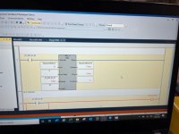
BSL instruction on Connected Components Workbench

Fraser

Member
Join Date
Mar 2023
Location
Scarborough
Posts
5
I’m working on a conveyor project for work. We’re trying to install a few diverts to carry product directly to one of two trailer doors. I have some PLC experience but it’s limited. I’m trying to teach myself how to use a Bit Shift Left/Right instruction on CCW since it will be required to sequence the boxes to the two diverts. I had the BSL instruction working on a test program I created to learn the instruction but I’ve hit a wall when trying to use that instruction once I add it to the program I’m writing for the conveyor and uploading it to the actual controller. For some reason the instruction works differently on the controller even though as near as I can tell I’ve set them up exactly the same.

On the simulator when I execute the instruction it seems to add a bool bit to the array (represented by a check mark) and it moves down the array as I continue to go high and low on the execute input. This is what I expect it to do. However when I do the same thing on the controller using photo eyes to trigger the instruction it gives me a significantly higher numeric value on the sequence bit address (SequenceBSL[1]). No bool bit populates the array and moves down the array as I continue to execute. I’m not sure what the numeric value represents in the SequenceBSL[1] address. I suspect the issue has something do with that but I haven’t been able to figure out how to resolve it. I’ve uploaded some pics of the instructions for the controller and simulator programs to show the difference. Any guidance on this issue would be appreciated. Thanks.

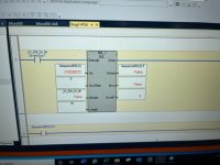
Contoller BLS instuciton array.jpg Contoller BLS instuciton.jpg Simulator BLS instuciton array.jpg Simulator BLS instuciton.jpg
 
I’m working on a conveyor project for work. We’re trying to install a few diverts to carry product directly to one of two trailer doors. I have some PLC experience but it’s limited. I’m trying to teach myself how to use a Bit Shift Left/Right instruction on CCW since it will be required to sequence the boxes to the two diverts. I had the BSL instruction working on a test program I created to learn the instruction but I’ve hit a wall when trying to use that instruction once I add it to the program I’m writing for the conveyor and uploading it to the actual controller. For some reason the instruction works differently on the controller even though as near as I can tell I’ve set them up exactly the same.

On the simulator when I execute the instruction it seems to add a bool bit to the array (represented by a check mark) and it moves down the array as I continue to go high and low on the execute input. This is what I expect it to do. However when I do the same thing on the controller using photo eyes to trigger the instruction it gives me a significantly higher numeric value on the sequence bit address (SequenceBSL[1]). No bool bit populates the array and moves down the array as I continue to execute. IÂ’m not sure what the numeric value represents in the SequenceBSL[1] address. I suspect the issue has something do with that but I haven’t been able to figure out how to resolve it. I’ve uploaded some pics of the instructions for the controller and simulator programs to show the difference. Any guidance on this issue would be appreciated. Thanks.

The numeric value is just the decimal equivalent of the binary you are looking at. For example your shown value of 218038272 will have bits 16-31 high except 28 and 29.

In the actual controller you have the length set as '16' whereas in your simulation it is set at '32' -- Since you are addressing a 32-bit DINT, a length of 16 will result in only half the word being used. Put simply, your bit is being loaded in halfway through the word. If you watch the upper half of the word (bits 16-31) you will likely see bits moving as you expect.

Disclaimer: I'm quite familiar with BSL in RSLogix, but have never used CCW for programming.
 
I am suggesting something similar to what @plvlce said.

The simulator emulates an actual Micro8xx PLC, so it may not emulate all 32-bits of the DINT that are being shifted: if the emulator "sees" you are only interested in 16 bits, it may not emulate the shift the bits from bit 15, the last bit, to bit 16 and beyond.

However, in the actual Micro8xx PLC, when you tell the BSL instruction that the 16 bits are in that DINT with tag name SequenceBSL, then every time that BSL instruction shifts the low 16bits, it shifts all 32 bits in the DINT, from bit 0 through bit 31, even if the last bit of interest is bit 15 and is the bit unloaded to the Unload pin of the BSL instruction.

Note that the BSL instruction does not provide an input pin to tell the instruction which is the first bit i.e. where bits are loaded into the bit "array" - new bits are always loaded to bit 0.

So, the value of a bit that is being "Unloaded" from bit 15 of that DINT is also shifted to bit 16 of that same DINT, and as more shifts occur that value eventually ends up in bits 17 through 31. For some reason the simulator does not emulate that behavior. Oh well, those unused bits of that DINT don't matter anyway, so you can ignore them.

Anyway, that's my guess.


That's similar to how the BSL/BSR work in the other AB platforms. The "length" of the shift affects where the new bit is loaded in the BSR and where it's unloaded in the BSL, but all the bits in the word shift. For instance, in the 500 world, if your length is 20, then both 16-bit words get shifted by one. I suspect that that's what's going on here too, but I've not done a lot in CCW and can't confirm.
 
That was the issue for sure. Once I changed the length to 32 it started functioning properly. I got thrown off because we tried several lengths in the simulator and it didn't seem to care.

Just to be clear so I fully grasp the concept If I create a DINT BLS instruction (32 bits) but only give the instruction a length of 16 the bit will be loaded half way through the array instead of the beginning?

Does this have anything to do with this least significant bit vs. most significant bit? I'm having a hard time visualizing why the instruction would behave this way. I thought setting the SrcOffset to 0 caused the instruction to load the bit on the first step of the array.

I really appreciate everyone's help with this. It definitely got me through a rough patch.
 
Just to be clear so I fully grasp the concept If I create a DINT BSL instruction (32 bits) but only give the instruction a length of 16 the bit will be loaded half way through the array instead of the beginning?


No, that is not what I am saying.

I am saying that if you give the instruction a length of 16, but the data (bits) are held in a DINT (32-bit) entity, then all bits will continue to be shifted left in that DINT past the 16th bit (bit 15, where bit 0 is the first bit).


Example: you BSL one 1 bit and then sixteen 0 bits into the DINT. On the last (seventeenth) BSL, that one 1 bit will be unloaded from the DINT, but that one 1 bit will still be in the DINT, just not in the first sixteen bits used by that BSL instruction:
bit 31 of DINT
|
v
0000 0000 0000 0001 0000 0000 0000 0000 <bit 0 of DINT

<= direction that BSL-shifted bits will move
 

Similar Topics

Hello everyone! I am in the middle of converting an RSLogix 500 program to RSLogix 5000. I made an array of INTS called B3 and have been using...
Replies
3
Views
1,820
I am using the BSL instructio in a micrologix 1500. It always indexes from the 35th word bit 0. For example N17:35/0 will be where it loads the...
Replies
7
Views
3,272
I am experimenting with the BSL instruction in LogixPro and have run into a problem. The goal of my program is as follows: track bad products...
Replies
14
Views
13,767
Ok, I got my BSL instruction doing what I want it to do, kinda. I am using it in a ML1000, in the instruction set reference manual it says "If...
Replies
7
Views
3,011
Hello all, I have a quick question regarding some numbers in my MicroLogix 1500 project. Basically here is the situation. We have a quartech 2800...
Replies
9
Views
5,068
Back
Top Bottom