Ken Roach
Lifetime Supporting Member + Moderator

This is a little OT, but I would like some general input.
I have an machine control cabinet with an HMI as well as numerous standalone LED-bulb indicator lamps. Most of those indicators are driven by ordinary general purpose PLC output modules. One is driven directly by a VFD and another by a safety relay.
Because the application is unusual, we have an industry consultant who has crane industry (CMAA and ANSI standards are involved) experience.
He asked that I add a "Push To Test" button just for the indicator lamps, and furthermore wants it to be hardwired to the lamp indicators.
If I wire a push-to-test button daisy-chained to the positive terminal of each lamp, that will let any of the PLC outputs "back feed" to drive all of the lamps.
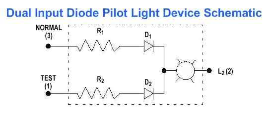
To avoid that, I could install a bank of small relays, so that I can individually apply +24V to each of the lamps in parallel to the PLC output. Or, I could install a bank of terminal blocks with diodes to block backfeeding.
But both of those seem wasteful of wiring and panel space.
My alternate proposal is that the lamp-test button only physically wires to itself and to a PLC input, and that the PLC reacts to a lamp-test request by turning on all of the lamps, then turning them each off one at a time.
That allows "push to test lamps" button to also mean "push to test DC power, PLC run mode, and control cabinet input and output fusing".
I could also treat it the way malfunction indicator lamps work on your car; when you start the car, they all light up, and the don't turn off until the associated self-diagnostic system completes its function. There are a couple of indicators for subsystems that can benefit from operator-initiated testing instead of functional demand.
Am I missing an obvious way to wire a lamp-test feature that doesn't involve a bank of relays or diodes ?
If you saw a "Push To Test" or "Push To Test Lamps" button on a control cabinet, would you expect it to solely test the indicator bulbs themselves ?
I have an machine control cabinet with an HMI as well as numerous standalone LED-bulb indicator lamps. Most of those indicators are driven by ordinary general purpose PLC output modules. One is driven directly by a VFD and another by a safety relay.
Because the application is unusual, we have an industry consultant who has crane industry (CMAA and ANSI standards are involved) experience.
He asked that I add a "Push To Test" button just for the indicator lamps, and furthermore wants it to be hardwired to the lamp indicators.
If I wire a push-to-test button daisy-chained to the positive terminal of each lamp, that will let any of the PLC outputs "back feed" to drive all of the lamps.
To avoid that, I could install a bank of small relays, so that I can individually apply +24V to each of the lamps in parallel to the PLC output. Or, I could install a bank of terminal blocks with diodes to block backfeeding.
But both of those seem wasteful of wiring and panel space.
My alternate proposal is that the lamp-test button only physically wires to itself and to a PLC input, and that the PLC reacts to a lamp-test request by turning on all of the lamps, then turning them each off one at a time.
That allows "push to test lamps" button to also mean "push to test DC power, PLC run mode, and control cabinet input and output fusing".
I could also treat it the way malfunction indicator lamps work on your car; when you start the car, they all light up, and the don't turn off until the associated self-diagnostic system completes its function. There are a couple of indicators for subsystems that can benefit from operator-initiated testing instead of functional demand.
Am I missing an obvious way to wire a lamp-test feature that doesn't involve a bank of relays or diodes ?
If you saw a "Push To Test" or "Push To Test Lamps" button on a control cabinet, would you expect it to solely test the indicator bulbs themselves ?