Closed loop control of liquid through a Solenoid Valve

kunalv

Member
Join Date
Sep 2019
Location
India
Posts
28
Hello,

I am trying to make an Automatic Coolant Dispensing station for my client. This unit will be stationed next to a CNC Machine to monitor the coolant in the sump.

I have drawn a schematic of the unit. Feel free to suggest changes or improvements if any.

Quick description of requirement :-

- There are two flow streams entering the dispenser : one of water and one of coolant concentrate. Both are introduced under gravity. The water will be fed through the plant's overhead tank through a pipe, while the coolant concentrate will arrive through a 100Ltr tank in my unit.

- I am going to install flow sensors in both lines followed by Solenoid Valves in each line.

- Both lines shall then be fed into a Static mixer to carry out the mixing.

- The flow-rate of water varies. How do I control flow-rate of coolant to match that of water? For eg. If I am going for a 1% concentration of mixture for a 100 Litre total addition which makes it 1 Litre of concentrate mixed with 99 Litres of water, can I use a PLC to proportionately control the opening & closing of both the valves as per the input from the Flow sensors?

These are the flow-sensors I am going to use - https://broiltech.com/plastic-helical-rotor-flow-sensor-and-meter/45

I have sourced PWM Valves and a Controller from Asco (Emerson), but they are out of my budget. Any other way I can approach this application?

Guidance will be appreciated :)
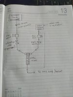
WhatsApp Image 2020-05-27 at 14.20.18.jpg
 
Last edited:
To get a correct mix I don't think you have much choice but to control both flow rates, however, if the flow rate of the coolant is reasonably constant then you could just use a controller on the water side, however, this is not ideal and dependent on the accuracy you require. The best solution is if you could dose known quantities into a buffer vessel & then mix. but not knowing your system it is difficult to come up with an accurate answer. If this is just coolant for cutting it probably does not need to be that accurate, however, I'm no expert in cutting fluids so reserve my judgement.
 
There are many other variables to consider BUT based on info provided, here goes....Does the system allow for batch mixing? Can you mix a full batch in your static mixer and then send it all to the CNC sump. If you do this, you can do away with the proportional valves. If the process is critical, I would have flow meters downstream of the valve to monitor flow and/or leaks in the event of valve failure.
 
[ignore this, I didn't read the last couple of lines of the OP. what is the budget?]


I think you are looking feed-forward control. Specifically, there would be a PID on the coolant concentrate valve that controls (i.e. has as its PV) the coolant concentrate flow to a setpoint that is 1% of the measured water flow. So a really terrible schematic would be


Code:
                                     +--------+
                                     |  PID   |
                                     |  ===   |
                                     |        |
[water flow ] => [Multiply by 1%] => |SP    PV| <= coolant flow
[measurement]                        |        |
                                     |     OUT| => coolant valve position
                                     +--------+
What determines the total flow rate? If it is the sump level, then use the water valve to control sump level i.e.

  • LevelPID.SP = desired sump level
  • LevelPID.PV = sump level
  • LevelPID.OUT = water valve

PID level control may be overkill, of course. Maybe the level control is "bang-bang, open water at low level sensor, close at

high level sensor;" but that does not change the feed-forward scheme.


Caveats

  • Ignores inaccuracies in flow measurement
  • Mixing inaccuracies due to response time of feed-forward control, especially if water flow is bang-bang, can be ignored
 
Last edited:
Flow meters after a valve is not a good idea, if it is open ended then flow will tend to be detected as the pipe empties so flow meters should always be upstream of a shut off valve to keep the flow meter full. I have already suggested a buffer tank as I believe the mixer to be in-line so will not hold any real amount. The only other thing I can suggest is that you use manual valves to control the flow of each, batch both solutions at the same time but ensure the lube will finish before the water by enough based on fastest flow, by using batch in parallel it could be possible to tune it fine enough where the water is slightly behind the lube so it adds a small quantity at the end to make up the batch. This does mean a slug of water without lube but should mix quickly in the sump. This way there is no need for PID control, batch i.e. count pulses instead of flow so although not a true mix as the last would be water should work quite well.
Problems with this is someone will decide to alter the manual flow control valves & mess it up but using batch in parallel is a far easier method providing you get the timing right.
 
Last edited:
Just looked at the flowmeters you are using and these are really for batch not flow, to get accurate flow takes time by counting the pulses or calculating the time between pulses to get flow rate, again not a good idea. In this situation batch in parallel is the best solution given the equipment you have.
 
Guys, one quick question about your replies before I go through them in detail and come up with more queries. Apologies if it sounds stupid.

What's the difference between Batch Mixing & Flow Mixing with respect to this application?

I have not considered a separate tank for mixing so far due to lack of space & the general need to have a compact equipment. But if I do go for a tank (last resort), why would I need a static mixer?
 
You might be able to connect the flow sensor on the water stream directly to a dosing pump for the concentrate once you have it set up for "flow pacing", the dosing pump would run at a rate proportional to the flow signal.

The liquid facing parts of the pump need to be made of materials compatible with the chemistry of the concentrate.

The flow meter and pump input signals need to be electrically compatible.

There would not be a need for a PLC, but some care would need to be taken to ensure that a failure of the dosing pump is detected and that the system stop if that happened.
 
Batch is where you measure the volume produced, for example:
lets assume your flow meter gives 200 pulses per gallon and you want 50 gallons then 50 x 200 = 10,000 pulses. so in batching you want 50 gallons count the pulses from the flow meter until it reaches 10,000.
Most people scale the pulses so that the actual reading is in what ever measurement you want. Flow is where you measure the actual flow in say gallons per minute, obviously you would have to convert the flow pulses into actual gallons. Matching two fluids being blended in-line the best way is to control the flow for each i.e. water 10gal/minute lube 0.1gal/minute. But as you say you have little control over the flow rate and the fact you have pulse flow meters makes flow measurement a little more difficult.
To use PID to control the flow you will need to convert the pulses to flow per minute or what ever the time base is. on such a small amount this would be a bit of a challenge but possible, however, the smaller the sample for conversion the less accuracy you will have.
The best solution I can offer is that you manually set the flow rates with manual adjusted valves so in essence water flow is say 100 gals per 10 mins and lube is 1 gal per 10 minutes, then open both control valves, count the pulses when the lube gets to 1 gal, stop the flow, when the water gets to 99 gals close that valve.
At least you will have dosed the correct amount, however, depending on the settings of the manual valves you may not get a full mix at the end, so lets assume the flow is controllable enough to allow the water to get to 95 gals and the lube to 1 gal, close the lube valve & finish off with 4 gals of water.
Using flow instead of batch there could be considerable errors as when one of the flows increases or decreases the reaction time of the PID & mechanical properties of the valve could cause considerable errors, many systems use what they call bump less start on on initial starting a pre-set value is put into the PID control to set the proportional output to a fixed amount, the idea is that rather than the PID assuming no flow it would not ramp up to full output but a level that under normal will produce the correct flow rate, after a short time the PID is put into auto control so it is closer to the normal running conditions and can quickly control around smaller fluctuations.
One other thing you must consider is how fast these pulses are and the PLC you are using, some have a small amount of inputs that will react to fast pulses and possibly I/O interrupts to catch fast pulses, most PLC's will not be able to catch pulses from flow meters as the update time of normal I/O + scan time of the program is probably slower than the pulses. What PLC are you using ? Some do have high speed functions, however, some will require the addition of a counter module and these are not cheap.
Regarding the mixer I assume if this is what is commonly called SUDS Water/oil mix then the mixer is to homogenise the two dissimilar liquids.
On a lathe for example, an operator will make up his mix manually, put it in the sump & run it round creating the mix. I think because the machines you are feeding are probably some kind of automatic process they may not want unmixed lube to pass over the work piece & cutters. I'm no expert on machining so I think it would be a good idea to find out things like mix accuracy, could it be batched etc. It does look to me if this system is on standby until one or more of the machines calls for a top up, in this case without a buffer tank then flow control is best. I think you need a bit more information.
 
If you went with the 1/4" (4200 pulse/litre) flow meter for coolant and the 1.25" (52 pulse/litre) flow meter for water, and if they pulsed at the same rate, then the mix rate would be 52/(52+4200) ~ 1.2% i.e. near th 1% target, although the water flow meter is way oversized and the client is spending an extra 20% or so on coolant wrt the 1% target.


Anyway, then the trick is to make them pulse at the same rate, but if you can do that you can probably also get them to pulse at some ratio of rates, so you don't need to oversize the water valve.


What controls the water flow rate (e.g. sump level bang-bang or sump level PID)? Does it vary?


What kind of valve flow characteristic (e.g. equal percentage)?
 
It looks like there is no control on flow rate, the water is gravity fed & it looks like it's the same for the lube. He did say that the water flow rate varies considerably. There also seems some ambiguity on how the system will work for example, from the drawing it appears that this is an on-demand fed directly from the mixer to one or more machines. It is not clear although the OP talks about 100 gal where 1% is lube, this does not look like a batching system & the flow meters are pulse only (I suspect hall effect paddles). Therefore there could be an issue of speed to read these pulses, the OP has not told us of the PLC he intends to use. We need a lot more information as to accuracy, how it feeds is it on demand or for a batch.
I do agree that controlling the flow by restriction is a possible answer, however, with this being a gravity fed system there will be flow issues.
 
another very simple, low-tech, but coarse, approach:


Assume the water tank provides essentially constant head (water tank level variation is small wrt the drop from the overhead tank to the water valve).


Do the same thing for your coolant unit: have the 100l tank flow to a float-controlled, constant level sump open to the atmosphere (it can be covered, but be vented e.g. with a gooseneck).


This is gravity feed, so almost all pressure drop will be taken across the valves (see Caveats), and the head will be more or less constant, so the flow can be characterized for each valve vs. position, and the position of the coolant valve will be a strict function of the position of the water valve.


Specific characterization of the individual valves may not be necessary; if the flow meters are in place, then setting the water valve to 5%, 10%, ..., 95%, and finding the corresponding coolant valve position to achieve the 1% mix rate may be an acceptable calibration procedure for the system. Then all that is necessary is to find a way to have the coolant valve follow the calibrated characteristic using water valve position as the characteristic's input. This has the advantage of leaving the responsibility of positioning the water valve with the client.


Caveats

  • Static mixer introduces variable pressure drop, so the assumption of constant pressure drop across the valves is a dubious one.
    • This may not be an issue when using the system characteristic calibration method above
  • The system characteristic may change over time, so providing the client with a procedure to re-calibrate, and to re-enter a new valve-to-valve characteristic (or to call you back to do it for them).
  • I have no idea how to implement the system characteristic in analog form (grind a cam? build a physical nomograph with sticks and pivots?). It's trivial with a PLC of course, and there are fairly inexpensive options there, but the OP said a controller breaks the budget. There are also simpler units (dare I suggest a custom SBC?) that could be programmed to do this specific task without going the full PLC route.
 
Last edited:
the flow meters are pulse only (I suspect hall effect paddles)


the URL from the OP (does anyone else's scroll wheel not move that page?) says helical flow meter with Hall sensor, Reed Sensor and pick up coil options, which I assume are for the pulses.
 
There is another way, if using at least one controlled position valve. The flow meters will come with a "K" factor, this is the number of pulses per volume. I'm going with litres here after all, I'm British. I have done many systems using pulsed flow meters some of these were using pulse only, Using the "K" factor, sample the pulses over a period of say 1 second and using the K factor calculate the flow rate per second. use some maths to manipulate either the water or the lube flow valve, I don't think you would need to use a PID but if so use it as only PI no derivative, it would need to be reasonably fast loop and there will be inherent delays in adjustment but could give you a reasonable mix concentration.
 
Yes you are right, most are hall effect, basically these are a sized orifice with a paddle wheel, each paddle will have a magnet and either a coil or hall effect sensor built into the body. These must be fitted before a control valve or shut off or half empty pipe will cause errors. I have used the Burkert ones, very reliable, however, any contaminants can cause the bearings on the paddle to stick, but they are pretty reliable. The systems I have put in place require us to calibrate them so rather than rely on the given "K" factor, I put in a calibration procedure for example: Dose a quantity into a vessel, weigh the vessel or if calibrated vessel (a known quantity), enter the number of litres or what ever into the HMI cal Screen and it would calculate the K factor. To be honest, it was rarely outside of plus/minus 0.7 pulses out from the stated K factor but for accuracy you have to use floating point maths as 57 pulses per litre versus 57.4 gives large errors on higher volumes.
 

Similar Topics

So it looks like i am stuck with an old reliance DC drive on this project instead of the powerflex dc w/ 22-COMM-E. That being said i am trying to...
Replies
0
Views
1,188
I have just received a RFQ for a closed loop pumping system (hydroforming ). I did a small system like this about 8 years ago in a SLC. It worked...
Replies
3
Views
2,303
Is it possible to operate a unidrive sp in closed loop vector contol to drive a roller that is turning in a cradle type configuration and the...
Replies
2
Views
1,999
Hey guys, Im not sure how appropriate this is for this forum but I have received alot of help from you guys in the past. Im taking industrial...
Replies
4
Views
2,162
HI, i am trying to control DC motor and encoder,by using plc200.cpu222 HSC 0,and analog output card. can you help me by giving me a hint about the...
Replies
2
Views
1,956
Back
Top Bottom