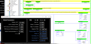
Velocity Control PID in CompatLogix

This will be interesting.

You must be assuming the fan is pressurizing the cabinet to keep a small positive pressure. This would keep the dirt/dust out. That hasn't been confirmed by the OP yet.


Yes I noticed that too;-), although it should not matter, as it changes only two signs in the differential equation.


Well, it changes a lot more than that (the model has code that keeps the pressure component from going negative i.e. to the wrong side of ambient).
 
Here we go

https://github.com/drbitboy/pressure_control_via_fan_velocity


The purpose was to model the OP's system as I interpreted it, to see if a PID driving a fan speed ramp could control pressure in an enclosure; I think it reduces to ID control of the pressure, similar to controlling compass direction with a steering wheel or tiller, or climb/descent and compass direction with a joystick in an airplane.


Please be kind.


TL;DR


The environment is [AdvanceHMI + VS/VB 2019 + MicroLogix 1100], but the code is all there (*.vb files for the VB stuff; .pdf report for the .RSS file) to look it over if you do not have that environment.


You can change most of the parameters, although some will make more sense to change while the PID is not in auto mode.


For the default parameters*, a Kc gain of 25 seems to do a slow but successful job of controlling the pressure via the fan ramp.


* the default parameters were chosen by eye:

  • 10ft**3 enclosure
  • Leaks rate is 0.1 ft**3 s**-1 at 1PSIG
  • Fan at 100% speed generates 1PSIG max pressure i.e. at zero flow
  • Fan at 100% pushes 1ft**2 s**-1 max flow i.e. at 0PSIG
  • Fan performance curve (PSIG vs. Flow) is modeled as a quarter of a cosine curve ;-)
  • Fan max pressure and max flow parameters are linear with speed


Caveats

  • Operationally, before switching to auto mode, ensure the system (VB executable) is
    • at steady state,
    • with SP = PV,
    • Output = 50%,
    • and Ramp = 0.
    • I think my PID implementation is overly clever with the bumpless transfer, so if the SP and PV are not close when switching to auto mode it just accepts the error as normal and does nothing in the P term.
  • The pressure model runs on a 1Hz cadence with the PID in auto and a 0.5Hz cadence in manual (because the MicroLgx1.1k RTC runs at 0.5Hz;-)).
  • It all looks and behaves reasonably, but I have not thoroughly reviewed the math; specifically
    • I did Implicit Euler from memory/imagined first principles, so I am probably playing fast and loose in its implementation
    • The PID should be okay, but I have not tested much beyond the P term.
  • There are several bells and whistles missing from the PID implementation as it was not meant to be anything more than enough to fiddle with the pressure control at hand; feel free to add whatever is missing
  • The PID should be in a separate program file; feel free ...
  • I should have modeled this as a vacuum, but since everything modeled without second-order pressure effects, the same code works either way if the pressure is interpreted as a vacuum instead of a positive pressure.
  • I implemented pressure-driven flow (leakage?) as linear with the square root of the driving pressure difference i.e. turbulent flow regime (Re > X,000); if this is actually leakage, then it is likely that any leakage flows are actually laminar, and the flow will be linear with pressure difference, not its square root.
  • Minor, but(t) ugly, point: but I have a feeling the timer logic on Rung 000 plust the logic on Rungs 0003 and 0004 are several times more complicated than what they need to be to implement that functionality; maybe putting the PID in an STI would eliminate 90% of that.

xxx.png
 
Please be kind.
That must be directed at me.


I will sit back and watch. You should know that you can't simply treat air flow like water. As pressure increases, some of the air flow simply increases pressure and doesn't increase the volume. It does increase the density.


However, if this is simply a matter of pressuring a cabinet a small fraction above atmospheric then one isn't compressing air much.


I do want to stress that we have made the mistake of pressuring a cabinet 1/4 psi above atmospheric which resulted in the cabinet looking bloated. 1/4 psi over all the square inches is a lot of force. The cabinet was ruined. Ouch.
 
That must be directed at me.
not'tal, no. I made a lot of simplifications to get this done. e.g.

You should know that you can't simply treat air flow like water ...
Mdelling air as and incompressible flow? yes, I know I am doing that, but it is being done over a reasonable range: my assumption all along is that this is less than 1PSIG (it's a fan), or even a quarter-PSIG, per your note below and mention in earlier post.


I do want to stress that we have made the mistake of pressuring a cabinet 1/4 psi above atmospheric which resulted in the cabinet looking bloated. 1/4 psi over all the square inches is a lot of force. The cabinet was ruined. Ouch.


Oh yeah, small PSIG times large SI is a big deal. My favorite trick application of a similar effect is to let a large, flat, low-density thing (e.g. hollow door) fall over from on-edge down onto the flat garage floor - for the last inch or so the air cannot escape fast enough and so it cushions the fall.
 
I did some more tuning tests, using a step change of the setpoint, and I think the in-effect integral control approach (controlling second derivative i.e. fan speed ramp with P of PID) does not work well: any gain I tired gave a near 100% overshoot and significant cycling.


By the time the PV crosses the SP, there is too much wind-up in the fan speed that the P (I) cannot stop the excessive overshoot. I suspect this could be shown to be a property of the fundamental maths of applying Integral-only control to an integral (accumulating) process.


I said I had successful control results early with a Kc of 25, but I must have misinterpreted something wrong there.


One possible way to make it work might be to force the PID output to 50% when the PV crosses the SP, so it starts recovering sooner and lessen the overshoot.


That said, I think this model shows this approach - PID control of the second derivative of the process - is a non-starter. That was suggested early in the thread; this is just the proof.
 
drbitboy, everything can be calculated. That includes the PID gains. There is no excuse for 100% overshoot or any overshoot if it is not desired.
Are you sure you are controlling the second derivative of the PV? Usually that is very "noisy" due to quantizing error and sample jitter

The second-derivative property is a fundamental characteristic of the OP control scheme; it is not not due to quantization or sampling.


To first order, the pressure in the enclosure is linear with the quantity of air in the enclosure (Ideal Gas Law: PV = nRT); V, R and T are constant (to first order), and n is proportional with volume of Air, so P ~ Air; so pressure (a proxy for quantity) is the "zero-th" derivative.


Each rotation of the fan moves a quantity of air into the modeled enclosure. The speed of the fan is linear with RPM or RPS, so speed is thus linear(-ish) the rate of air moving into the enclosure, so dPressure/dt ~ dAir/dt ~ FanSpeed: first derivative.


The PID (P only; Reverse-(re-)Acting; Ti = Td = 0) executes about once per second (~1001ms, if the free-running clock of my MicroLogix 1100 is to be trusted); each time it executes the 0-100% PID CVs's difference from 50% is assigned as the ramp of the fan speed, and that assigned value of the ramp of the fan speed is scaled by the delta time and that product added (accumulated in) to the fan speed, so PID output ~ ramp value ~ dFanSpeed/dt ~ d2Air/dt2 ~ d2Pressure/dt2, so yes, I am controlling something that is in effect the second derivative of the PV (pressure).


I am modeling the process, so there is no measurement noise or jitter per se, other than possible issues in the Implicit Euler convergence, which I am not seeing.


There is some non-linearity in the response because as the pressure changes the leak rate changes, so dPressure/dt ~ (FanFlow(Pressure,Speed) - LeakRate(Pressure)) / Volume, but those are all smooth functions and the absolute pressure is modeled as constant, which it is to first order, so the basic behavior is consistent.


So it is an accumulating (integrating) PV being controlled in effect by an accumulating (Integral-only) control of fan speed, the latter via the P term controlling the fan speed ramp.


It's as if I told someone to turn a car initially going east on a parallel 1minute south of the equator (~ 1 nautical mile) to move to the equator by rotating the steering wheel CCW by the magnitude of their current south latitude (turning left initially) once per 10 minutes (of time), and vice versa after they cross the equator: they would continue turning harder and harder to the left until they hit the equator, at which which point they would be going north and east but still turning left. So they would cross equator and start turning less left to remove the accumulated turning-left "wind up" in the system - they have been only turning the wheel more and more CCW because they were always south of the equator. As long as the car never ends up going directly north, the same thing happens even if the gain value is different i.e. if I twiddle the steering linkage, or change the period of adjustments.


The Integral (Reset; I in PID) of the PID algorithm is for dealing with change in system offset; it cannot be used on its own, i.e. without P, to control a system that is itself integrating.


In the OP's situation, with not the fan speed itself, but with fan speed ramp as the CV of a PID to control pressure, the P term of the PID effectively becomes an Integral control of fan speed, and there is no Proportional action in the [fan speed vs. pressure] system.


If I reduce the ramp gain*, that reduces the rate at which the system will approach the new setpoint, so the duration of wind up accumulation will be longer, so the wind up will be about the same, and will also be un-wound more slowly, which is probably why I am seeing very little change in overshoot across various gain values.


No amount of math or calculation is going to fix a fundamentally flawed system.


* or increase the update time, which is in effect the same thing as reducing the gain
 
Keep in mind that the OP is using a fan, not a positive displacement pump. The pressure that the fan can produce will be related to its rotation speed. It is a non-linear relationship but it is effectively non-integrating as a physical device even in the absence of leakage. Even in a deadheaded system the pressure to settle as some value.

The control of acceleration as the CV adds an integrator to the system. However, because of that, the last thing you want to do is add your own integrator in the control law. You would be much better off adding a derivative term. But that brings in the possible issues with noise that Peter talks about.

Keith
 
Keep in mind that the OP is using a fan, ...


Yah, I modeled the fan performance curve as the first quarter of a cosine cycle (zero to half-pi). Not accurate but close enough for modeling: it will change the actual response but not the general behavior.


The only purpose of the model was to investigate if the control scheme described in the OP was feasible, even though intuition suggested that it was not.
 
We are assuming it is a non-integrating system. That means the pressure in the cabinet will drop to ambient when the fan stops.
Assume there is one time constant. Let's assume the air will reach ambient in 2 minutes. It takes about 5 time constants for something to decay within 1% of ambient so assume the time constant is 24 seconds or any number 10 seconds, 30 seconds, it makes no difference. Note that we are assuming a time constant and it isn't really. Assume the pressure will go up 0.1 psi for 1 scf of air
https://en.wikipedia.org/wiki/Standard_cubic_feet_per_minute
assume the fan can supply 1 scfpm.
The plant model will look like a simple low pass filter only now you must calculate the decay constant as a function of time constant as opposed to just fudging it.
A PI controller will be needed but the system is non integrating. This will avoid the proportional droop. There is no need for a derivative gain because there is only one pole due to the one time constant. Now go for it.
 
drbitboy, all your effort and the op gave up after 2 posts and 5 days ago, l know you are enjoying doing it, but the op has offered nothing, no answers to all the assumptions.
 
Agreed Peter, This seems to be happening on most posts at the moment.
I too am getting a little fed up of these posts I don't mind helping anybody but please give us some relevant information. what is the actual process. what are the problems what have you got so far, what equipment are you using etc.

I agree - but people will get a 17 page thread answering a simple timer question though.
 
Originally posted by Peter Nachtwey:

A PI controller will be needed but the system is non integrating. This will avoid the proportional droop.

This assumes that the OP uses the control output the way he SHOULD use it; as a speed command to the fan. If he uses the control output the way he proposed in the initial post it is more like a motor operated valve application. In that case there would be no proportional droop since ANY error would create a proportional response at the control output that would cause the speed to continue to change (within the command resolution of the drive) until there is no error.

The moral of the story is the initially proposed command method is not the best way to approach the problem.

Keith

edit: I should clarify. No matter how you control it, the plant is non-integrating. As a programmer you can stick a software integrator in the command path but thaty doesn't change the fact that the plant is non-integrating.
 
I have some videos on controlling non-integrating systems with one pole.
Some how part 1 and 2 got lost but they covered P only and I only so they aren't that important.
Alpha is the corner frequency or open loop band width 1/alpha is the open loop time constant.


There is no need for a derivative gain. It will not help.


Part 3
PI control

https://www.youtube.com/watch?v=E6tH01GGxDg

Part 4
computing the PI gains using direct synthesis

https://www.youtube.com/watch?v=ZB1sd5LWugc


None of this matters is you can't compute the open loop gain and time constant so I included a video on simple system identification.
https://www.youtube.com/watch?v=qzr6eL90Aok&t=8s


I agree - but people will get a 17 page thread answering a simple timer question though.
As I pointed out, nothing is really linear in this system. or the purposes of this forum it should be simple. I can make it more complicated.


I were teaching college students they would need to be able to write the non linear differential equation(s) for the system or fail.


You don't go to college just to learn how to tweak gains until it works.
 
[Update: I just realized I am being trolled; to which I can only say "Well played, sirs. Well. Played." ;)]


I have fully understood from the beginning that the system is non-integrating wrt fan speed; that is blatantly obvious, a little interesting, and irrelevant.


I don't know how I can say it more plainly: the system is integrating wrt the controlled variable i.e. wrt speed ramp slope i.e. wrt dSpeed/dt. The only caveat is that this applies over the controllable range of the fan speed only, but that is the only range of interest, otherwise it is bang-bang, not PID, control.


It has nothing to do with the model being a "software integrator" - I could have as easily picked second-order, physically reasonable fan and leakage models that would provide an exact solution for the pressure dynamics.
 
Last edited:

Similar Topics

The is the first system that uses complex or imaginary poles. Complex poles oscillate. RLC circuits, masses on springs, pendulums, masses on...
Replies
19
Views
17,001
So you thought you would take the weekend off! No way. The link below is saying download me! Give me a try! The link is to a spreadsheet that...
Replies
15
Views
23,452
A query for the motion control experts: I have an app where I measure the position (encoder ∝ K * angle) of a rotating device, and use that along...
Replies
15
Views
3,729
A bit of background here: We use an incremental encoder with a counting module in our PLC configuration. Using dual phase / quadrature counting...
Replies
26
Views
8,891
I have a 1746-QV. I just replaced one that had gone bad. I am looking for an electrical schematic for it so I can attempt to repair it just for...
Replies
0
Views
1,606
Back
Top Bottom