Velocity Control PID in CompatLogix

Scratch that: I am not being trolled; I am (was) being dense.


What Peter and Keith were so patiently trying to get through my t'ick skull is that, because it is a well-behaved, decaying non-integrating system in pressure (for which fan speed is a near-proxy), a proportional-only controller with PV=pressure and CV=dSpeed/dt (fan speed ramp) is equivalent to an Integral-only controller with PV=Pressure and CV=Speed.


A PID controller with very low (or zero) gain (proportional reaction) but not too much integral reaction will always get there, albeit slowly.


Thanks for your kindness!
 
Last edited:
drbitboy, all your effort and the op gave up after 2 posts and 5 days ago, l know you are enjoying doing it,


Yah, but the source of my joy that you note was that I just started fiddling with a new toy: AdvancedHMI. So it was a case of a solution in search of a problem;); the OP wss a distant memory.
 
Last edited:
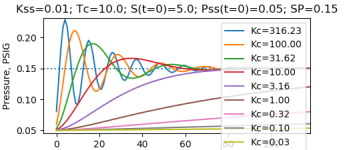
Per most of PeterN's suggestion, in Python; Kc of order Tc is slow but not awful.
xxx.png
Code:
"""
t = time, s
delt = 1s; time step and PID loop update; 1s for simplicity
S = fan speed
P or P(t) = pressure at time t
Pss = steady state pressure at constant fan speed
Tc = decay time constance, from P(t) to P(t+delt), toward Pss
Kt = e**(-delt/Tc); fractional decay, from P(t -> t+delt), toward Pss
Kc = Proportional gain for PID with PV=P and CV=deltaS/delt

Models
======

  Steady-state pressure

    Pss = Kss S

  Pressure dynamics

    dP/dt = (Pss - P) / Tc

    => 

    P(t+delt) = Pss (1-Kt) + Kt P(t)

    N.B. Assumes Pss constant over [t:t+delt];
         assumes instantaneous responses of fan speed and flow

  Fan speed

    S(t) = S(t-delt) + Kc (SP - P)

    N.B. Reverse-(re-)acting PID with 0 = Ti = Td

"""
import os
import sys
import matplotlib.pyplot as plt

if "__main__" == __name__:

  Kss = 0.01               ### 100% fan speed yields Pss = 1PSIG
  Tc = 10.0                ### Tc = 10s
  Kt = 2.71828**(-1.0/Tc)  ### ~ e**(-Tc 1s)
  oneminus_Kt = 1.0 - Kt   ### 1 - Kt

  S0 = 5.0                                  ### S(t=0)
  P0 = S0 * Kss                             ### P(t=0)
  SP = (S0 + 10.0) * Kss                    ### Setpoint

  for logKc2 in range(9):                   ### 0 to 8

    Kc = (10**((1.0-logKc2)/2.0)) / Kss     ### 3.16/Kss to 3.16E-4/Kss

    S,P = S0,P0                             ### Initial conditions

    ### Model Pressure over 10k steps of 1s
    ### N.B. assumes instantaneous fan and flow rate response

    lt = list()
    for i in range(10000):
      S += (SP - P) * Kc                        ### Controller re-action
      Pss = S * Kss                             ### Steady state
      P = (oneminus_Kt * Pss) + (Kt * P)        ### Decay toward Pss
      lt.append(P)                              ### Append datum to list

    if not logKc2: plt.axhline(SP,linestyle='dotted')
    plt.plot(lt,label='Kc={0:.2f}'.format(Kc))  ### Plot data

  ### Annotate and .show plot
  plt.title('Kss={0:.2f}; Tc={1}; S(t=0)={2}; Pss(t=0)={3}; SP={4}'
            .format(Kss,Tc,S0,P0,SP)
           )
  plt.xlabel('Time, s')
  plt.ylabel('Pressure, PSIG')
  plt.legend(loc='upper right')
  plt.show()
 
drbitboy,

Ambient pressure is steady state. You defined steady state incorrectly. The set point should be something like 0.1+Pss to get 0.1 psi over ambient. For simple simulation the ambient is 0 gauge or 14.7 psia


You have rigged the simulation so the ambient is not 0 so the response will always go to your set point. With out an integrator there will be proportional droop and you should never reach the set point but it appears that your simulation always reaches the set point eventually. That isn't right.


The differential equation should be dP/dt=(P(t)-Pss)/Tc
Now the pressure will decay towards ambient pressure when the fan is off.
This formula needs a forcing function or fan term. to make it

control at SP=Pss+0.1.
In a simple system like this the Ti should be about the same as what you call Tc. I don't like calling the plant time constant Tc. Tp, T0, T1 is OK but Tc should be reserved for the closed loop time constant or controller time constant, not the plant time constant.
 
drbitboy,

Ambient pressure is steady state. ...


Okay, either you are close, or you are trolling me. I suspect the latter, but just in case:

Cf. here

Steady state for this process includes the fan model with the fan running at a constant (i.e. "steady state") speed i.e. with the speed ramp at zero slope. We have to do this because the PID CV is ramp slope, and the PID is completely, utterly, and absolutely ignorant of fan speed.


In that case, the steady state pressure is wherever fanFlowIn(P,S) = leakageFlowOut(P)*, or, more specifically, where 0 = (fanFlowIn - leakageFlowOut) i.e. 0 = (accumulation rate), and pressure, the PV, is a proxy for accumulation, linear per the Ideal Gas Law. so it does not matter if we use PSIG or PSIA, because compressibility is a second-order effect that we ignore.


Also, we don't need Integral (re-)action in the PID itself (i.e. Ti is zero), because the CV is the ramp slope of fan speed, so proportional action inside the PID itself driven by error (SP-PV) is effectively providing integral action to the process fan speed via a non-zero Kc, and it is that effective integral action driven by error that eliminates any droop; there is no proportional action driving fan speed.


* or fanFlowOut(P,S) = leakageFlowIn(P), for pulling a vacuum in the enclosure; the formulae are the same
 
Last edited:
Okay, either you are close, or you are trolling me. I suspect the latter, but just in case:
I am not trolling you. I am trying to get you to think about if your model is correct. There is satisfaction in being able to figure this stuff out on your own. I like the fact you are willing to put the effort to try but I am teasing a little by not providing the answer.
Keep going.
Steady state for this process includes the fan model with the fan running at a constant (i.e. "steady state") speed i.e. with the speed ramp at zero slope. We have to do this because the PID CV is ramp slope, and the PID is completely, utterly, and absolutely ignorant of fan speed.
What happens to the pressure when the fan is off? Your model has the pressure always decaying to the set point when it should decay to ambient pressure.


In that case, the steady state pressure is wherever fanFlowIn(P,S) = leakageFlowOut(P)*, or, more specifically, where 0 = (fanFlowIn - leakageFlowOut) i.e. 0 = (accumulation rate), and pressure, the PV, is a proxy for accumulation, linear per the Ideal Gas Law. so it does not matter if we use PSIG or PSIA, because compressibility is a second-order effect that we ignore.
OK.


Also, I don't need Integral (re-)action in the PID itself (i.e. Ti is zero), because the CV is the ramp slope of fan speed, so proportional action inside the PID itself driven by error (SP-PV) is effectively providing integral action to the process fan speed via a non-zero Kc, and it is that effective integral action driven by error that eliminates any droop; there is no proportional action on fan speed.
You need an integrator. Either the process must be integrating or the controller must have an integrator. Otherwise you have proportional droop. You seem to thinking the cabinet is an accumulator. It would be if the pressure didn't decay down to ambient pressure without an input.


Lets see you try again.
BTW, I do hydraulic simulations all the time. That is what I do.

https://deltamotion.com/peter/Mathcad/Mathcad - Hydraulic Cylinder.pdf


I have the solution done. I am waiting for you.
 
What happens to the pressure when the fan is off? Your model has the pressure always decaying to the set point when it should decay to ambient pressure.
So, the fan speed is 0, and it is a constant i.e. steady state 0, and the steady-state pressure is ambient i.e. Pss = Kss S = Kss 0 = 0. So it is a special case of our steady-state model, correctly predicted by the steady-state equation
You need an integrator.


We have one.

The CV of the PID is the fan speed RAMP SLOPE i.e. CV dS/dt = (CV - 50) * scaleFactor, and THAT is our speed integrator. When the system is at steady state, the CV of the P-only PID is to 50%, so dS/dt = 0, which means S is constant i.e. at steady-state. When a SP impulse is applied, then CV moves away from 50% and dS/dt becomes non-zero, until the system is arrives at a new steady state, and S at some other value than the steady-state value it had before the SP impulse was applied, with P=SP so Error = (SP-P) =0. so the CV of the P-only PID has returned to 50%, so dS/dt is zero again i.e. S is at (a new) steady state.

Otherwise you have proportional droop. You seem to thinking the cabinet is an accumulator.
No I do not think that in the way you think I mean it.


But yes, it is an accumulator; specifically, pressure is an indication of the net accumulation of air in the cabinet (Ideal Gas Law), i.e. pressure change is the definite integral [∫ (fanFlowIn - leakageFlowOut(t))dt]. At steady-state, (fanFlowIn - leakageFlowOut) = 0, so pressure is constant.

I am waiting for you.


I am waiting for you to grok the significance of the red-letters above.


There was once a thread on a forum about whether a wind-only-powered device could go directly downwind faster than the wind (DDFTTW). I turns out the answer is yes, but the thread, which actually comprised several serial threads in that forum, was the longest thread on talkrational.net*, with tens of thousands of posts.


* which may be somehow related to this site, because the theme is similar,
 
So anything less than 50% will cause the fan speed to stop. An output of 0 stops the fan very quickly. I am assuming that is 50%, will not increase the speed? Does that seem right?


Yes, that is how the [AdvancedHMI+MicroLogix.RSS] works.


There is nothing magical about dS/dt=0 at 50%; if the PID's output (CV) range was [-100%:+100%], then dS/dt could be linear with CV with a zero offset (dS/dt = k CV).


The all-Python simulation does not calculate CV, but instead calculates dS/dt, or ΔS/Δt with Δt=1, so ΔS, at each iteration directly.


But the main point is that steady state is not at S = 0. but rather at dS/dt = 0 i.e. the fan is running at a constant speed, and I assume it is obvious that the steady pressure will be a function of that constant speed i.e. when fanFlowIn = leakageFlowOut, or to put it another way, when 0 = (fanFlowIn - leakageFlowOut), where the latter term is linear with air accumulation rate, dn/dt, from PV = nRT, which can also be written P = nRT/V or simply P = k n, from which it can be seen that P is a proxy for accumulation, and dP/dt = k dn/dt, so at steady state, the net flow into the enclosure is 0 = dn/dt = dP/dt.
 
Actually, a input of less than 50 would eventually result in the fan motor going backwards.


Yes, fan ramp (MOP?) input of less than 50%. Or greater than 50% and the fan motor would eventually run past 100% speed.

So the AdvancedHMI simulation limits fan speed to [0%:100%].

The Python simulation does not limit S, but that was just a numerical exercise anyway. Even so, the key word is eventually: for small setpoint changes and reasonable Kc values, S goes neither negative nor past 100%.

The important thing to understand is that the control algorithm is Proportional-only:

  • CV = Kc' Error + bias
with Ti = Td = 0, and bias = 50%, and

  • dS/dt = (CV - bias) * outputGain
  • N.B. this is not S = ...
or, for the discrete PID and AdvancedHMI model

  • ΔS = (CV - bias) * outputGain * Δt
running at 1Hz i.e. Δt = 1. So

  • CV = (ΔS / outputGain) + bias
And from above

  • CV = Kc' Error + bias
So the CV output of the PID will always return to the bias (50%) when

  • PV = S
  • i.e. (SP - PV) = Error = 0
The Python simulation

attachment.php


does the same thing, but simply removes the intermediate CV calculation by subtracting the last two equations above and assigning (Kc' * outputGain) = Kc to do

  • ΔS = Kc Error
  • S(t) = S(t-Δt) + ΔS
  • S(t) = S(t-Δt) + Kc Error
at each iteration. So that P-only controller on dS/dt is in effect an I-only controller on S, and the P-only control keeps moving S - implicitly via dS/dt - until the Error is 0 and steady, which why there is no droop.


So, I hope we're on the same page now ;)?


I never thought any of your models were suspect, but I did continually suspect problems with mine; my main suspicion was that we were talking about two different systems.
 
Last edited:
So, I hope we're on the same page now ;)?
You are cheating. You have set the bias to be equal to what the integrator terms should ramp up to.What if the set point needs to change from 0.15 to 0.1 or 0.2?
Also, if the controller output drops to 0 for some reason does the fan run backwards?


BTW, I dug up an old Mathcad worksheet I did 15 years ago and modified in a minute or two. I change the set point from 0.1 to 0.2 and show how to calculate the gains.
 
You are cheating. You have set the bias to be equal to what the integrator terms should ramp up to.

No, the bias is set to 50% (or 0% in the Python model, IIRC).

The requirement for a "bump-less" start and successful operation is that the system needs to be in a steady state when switching the PID mode from manual to auto i.e.

  • the CV (PID) output needs to be 50% (= bias, equivalent to zero ramp slope), and
  • the PV needs to be constant
    • This might be what you mean by the bias, and yes, if the PV is moving when the switch is made to auto, then there will be an offset similar to, but not the same as, proportional droop
  • the SP needs to equal to the PV
It is easy enough to do that manually for now. I don't see how that is cheating, because obviously that could be managed in the PLC.


We wanted to see if a PID control of ramp slope could control pressure, and it turns out it can, though slowly and poorly.


What if the set point needs to change from 0.15 to 0.1 or 0.2?


Once the switch-to-auto conditions are met and the PID is switched to auto, then it will do exactly what it is programmed to do: drive the ramp until the error is zero i.e. until the PV equals the new setpoint, even if it was in the middle of chasing a different setpoint.


Also, if the controller output drops to 0 for some reason does the fan run backwards?


No, not in the [AdvancedHMI+MicroLogix1100.RSS] model: the PID clamps its CV (output) to [0%:100%], which clamps the ramp slope to [-10%/s:+10%s]; the Adv.HMI VB code, which is where the model keeps track of the fan speed, clamps fan speed to [0%:100%].


Yes in the Python model, but

  1. that only happens when the gain is too high and/or the setpoint change is too big and the overshoot is significant, or the new setpoint is close to zero.
  2. the python code was only created to plot the behavior of a very simple version of the model
  3. so fan speeds over 100% or less than 0% are not a problem because the python code is only investigating the dynamics, and the fan running backwards makes sense (will show continuous behavior) in the model, though not in reality, of course.
  4. if the actual fan crosses zero speed or less while the ramp is negative, or crosses 100% speed while the ramp is positive, then that would be akin to bang-bang control, so we don't care because that is a completely different control scheme, as we are only interested if the P-only could control pressure in non-abnormal conditions. In the actual case with the Adv.HMI+ML1100.RSS model, it simply takes longer for the P-only-ramp to drive the error to zero.
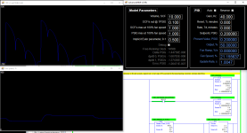
The image below is what it looks like.

  • The initial switch to auto was done at a steady-state
    • PV=SP=0.2PSIG;
  • then the SP was moved to 0.15PSIG and the controller drove error to zero;
  • then the SP was moved to to 0.25PSIG and the error driven to zero,
    • at which point there was a numerical round-off issue at the 1E-6 level
  • and finally the SP was moved to 0.20PSIG and the error driven to zero a final time.

xxx.png
 
Last edited:

Similar Topics

The is the first system that uses complex or imaginary poles. Complex poles oscillate. RLC circuits, masses on springs, pendulums, masses on...
Replies
19
Views
17,025
So you thought you would take the weekend off! No way. The link below is saying download me! Give me a try! The link is to a spreadsheet that...
Replies
15
Views
23,522
A query for the motion control experts: I have an app where I measure the position (encoder ∝ K * angle) of a rotating device, and use that along...
Replies
15
Views
3,739
A bit of background here: We use an incremental encoder with a counting module in our PLC configuration. Using dual phase / quadrature counting...
Replies
26
Views
8,932
I have a 1746-QV. I just replaced one that had gone bad. I am looking for an electrical schematic for it so I can attempt to repair it just for...
Replies
0
Views
1,608
Back
Top Bottom