"Writer's" Block

Join Date
Sep 2018
Location
Chattanooga
Posts
68
For some reason, I just cannot think of a solution to a problem concerning some basic ladder elements. I have tried thinking of the problem in a different context and still cannot come up with a solution. I am still a beginner.

I have a laser with a windowed output that services a conveyor. The conveyor is loaded from the side with a pneumatic cylinder. The conveyor only runs while an operator is monitoring the process. So during breaks the machine is shut off, only to be started again 10 mins later.

If a product is on the conveyor then the solution is simple enough. The laser will initialize the solenoid and raise a platform via the cylinder. The cylinder will de energize and drop the product onto the conveyor when the previous product proceeds beyond the laser's windowed output. When the XIC that monitors the laser goes TRUE then an RTO counts 200 ms then de energizes the output, dropping the product onto the conveyor to start the process over. Simple enough.

My block is coming from when there is no product on the conveyor. I dont want the operator to have to place a product on the conveyor to get it to run. I just want the operator to approach the machine, hit START, no matter if the conveyor has a product in the window or not. I can get the cylinder to raise no problem but cannot get the cylinder to drop the product because there is no input to initialize the drop.

As I type this out it seems like a simple problem, and any other day, I should be able to solve this no problem. But for some reason, today is the day. Any help is greatly appreciated.

Info on the laser: The discreet windowed output is set for 500mm to energize and 750mm to denergize. It also has an analog output with a 0-10v ouput. Both provide information to the ML1400 simultaneously.
 
Last edited:
Here is a snip of the program. THIS WORKS however the two timers will cause the cylinder to energize and de energize repeatedly without delay until the input is satisfied. I feel it has the potential to put undue stress on the equipment and i feel like iy could be done better.
 
Disclaimer: I dont' fully understand the process yet, maybe a diagram will help. This is just a quick first impression.

- I'm not sure it's a typo or not but do you realize you repeat the same logic? If you actually did this then you need to take a step back and understand how ladder works. Ladder does not work like your typical PC programming language. Your repeated logic will fight each other. Start by deleting run 0, 1, and 2.

- there also isn't enough logic there to tell me what's going on. What's counting up F8:3?

- Suggestion on the approach would be just work on getting the status correct and not worry about control the process first. Example, <stuff on> <stuff off> <parts on> <parts off>. If you can get these status bit to work good. Move on to control.

- Write out the control, plain English if you have to using the status you created.

- convert the description to ladder to control the process.
 
I just realized when I copy and pasted the logic it must have copied it twice, one set was in Rung edits and the other was the "To be Edited." Sorry I shouldve proofread first
 
So, Ive been toying around with it on the emulator and I may have a solution for it in this one attached.

A diagram is on the way, standby

The float (F8:3) is the analog output of the laser. Gives the location of the bar from 0-10. 10 being beyond the range of the laser.
 
Last edited:
Another suggestion, be strict and clear on tag description. F8:3 should not be a "conclusion" if it really is the analog of the laser measure. You can have a comparison of F8:3 to a variable or constant to determine if "A part is present" but not F8:3 itself.

It similar to stuff you learn elementary physic class, keep the UNITS consistent would go a long way to work out the logic. Keep your description correct would help you in getting the logic correct.
Can you elaborate?

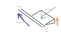
You say use a comparison, I have used a GEQ to compare the actual reading of F8 to a static number...Can you provide an example? Heres a very rough drawing of the process.

Simple Conveyor.jpg
 
... RTO counts 200 ms ...

This says ms, but all [Time Base] settings in the LD are 0.01 (cs). Did you bump the time base to make it easier to observe?

I am really looking forward to the diagram, because the description is throwing me: it says

The conveyor is loaded from the side with a pneumatic cylinder.

but then talks about "raising a platform" and "drop the product."

[never mind, I am just a bit thick; great diagram, btw]


Put simply, it sounds like the main rule is that you don't want to place a product on the conveyor while there is another product [present], whatever that means.

So, and I am really guessing here: you normally trigger the timer with a rising edge, and that rising edge is triggered by a product going from [present] to [not present] as sensed by the laser as product moves down the conveyor? And the transition from [present] to [not present] occurs when F8:3 goes from [less than 8.0] to [greater than or equal] to 8.0?

And the problem is that, if the machine is off for a break and is then turned while all products are [not present], then
  • the PLC and laser have been on the whole time even though the machine is off,
  • so the PLC/laser logic doesn't see a transition from [present] to [not present],
  • so there is no rising edge to trigger the timer
  • because the logic that provides that rising edge is already high,
  • so the timer doesn't start,
  • so the timer is never done,
  • so the cylinder does not get activated,
  • all for the want of a horseshoe nail
Am I close?

I apologize for the AR, track-every-electron detail, but it's duck debugging and how I think.

If I am close in that, then could you add logic that, when the Start button is pushed, somehow clears the logic that generates that rising edge?

  • If there is a product [present], then that source will be cleared by the laser anyway (GE(F8:3,8.0) will be False), and conveyor movement will eventually cause a rising edge on a future scan.
  • If no product is [present], then the Start logic I am suggesting will clear that rising edge trigger source for one scan, and the laser/GE(F8:3,0.0) will provide the rising edge on the next scan.

Hmm, is all you need an XIO on the Start button in series with the GE(F8:3,0.0)? Worst-case you might need to extend the button signal to ensure it is caught by at least one scan.

An equivalent option would be an XIC on the conveyor Running state; that's better because then you won't risk missing a short Start button event that falls between scans.
 
Last edited:
Can you elaborate?

You say use a comparison, I have used a GEQ to compare the actual reading of F8 to a static number

I think the suggestion is that F8:3 should not have a description [PARTS LOADER - NO PART PRESENT] because it is actually the part location whether the part is present or not, and it is the comparison instruction that determines [present] or [not present].

I have chafed at this before in RSLogix, i.e. that instructions are automatically labeled with a variable name, while the instruction result (of GEQ in this case) could be better described by something else.
 
Last edited:
My submission

I understand the siren song of timers, and have often succumbed to same. However I have found they are sometimes unnecessary; so I submit a timer-less approach for your consideration:

Drbitboy_part_drop.png


Summary
Assume the cylinder should be energized by default (Rung 0004), and only de-energize it (Rung 0003) when
  1. The conveyor is running, AND
  2. There is no part present, AND
  3. There is no re-start scenario active

Details
  • Rung 0000 sets up the re-start scenario
    • and is True for the first scan only after a re-start
  • Rung 0001 handles the re-start scenario
    • and is True from that first scan on re-start until the first time the platform is fully raised
    • It sets the re-start case on that first scan
    • and then seals the re-start case until the platform is raised
    • It requires an input or other method to choose when to detect or decide when the platform is fully raised
      • Proximity sensor?
      • This could also be handled in the PLC with a timer if a prox sensor is impractical
  • Rung 0002 handles the GEQ(F8:3,0.0) detection of part vs. no part
  • Rung 0003 chooses when to de-energize the cylinder and drop the part
  • Rung 0004 assumes the cylinder is always energized, except when rung 0003 says it should not be


Caveats
  • I am assuming I understand your process
    • Specifically, I am still not clear on how the part is "dropped onto the conveyor," and wonder if my timer-less approach could drop multiple parts at once.
  • I have not thought through PLC-startup issues
  • This may have a problem with laser measurement noise
    • There could be some de-energize/energize chatter across consecutive scans when F8:3 is near 8.0
    • I think your solution uses timers as a kind of debounce on the laser input
  • I originally had an XIC(CYLINDER ENERGIZE ON CONVEYOR RE-START)] ORed with the XIO(CYLINDER DE_ENERGIZE), but eventually convinced myself it was redundant.
  • The XIC(ALL DRIVES RUNNING) instructions on rung 0004 is probably unnecessary
    • In which case inverting the aggregate logic of the XICs and XIO (invert instructions and re-arrange as parallel ORs) on rung 0003 could replace rung 0004.
  • The XIC(ALL DRIVES RUNNING) instructions on rungs 0001-0004 could be replaced by [an XIO/NC and a jump around the other rungs] between rungs 0000 and 0001
 
Last edited:
Holy macaroni, I don’t have time to respond to such an in depth response atm. Later this evening I will sit down and read in detail and respond with my thoughts. Thank you very much.
 
Put simply, it sounds like the main rule is that you don't want to place a product on the conveyor while there is another product [present], whatever that means.
Precisely. The conveyor is a chain conveyor. It's only 2-4" wider than the product. Obviously, when two parts are placed on top of each other during process this becomes a headache for the operator.

So, and I am really guessing here: you normally trigger the timer with a rising edge, and that rising edge is triggered by a product going from [present] to [not present] as sensed by the laser as product moves down the conveyor? And the transition from [present] to [not present] occurs when F8:3 goes from [less than 8.0] to [greater than or equal] to 8.0?
Not exactly, currently the laser is a Keyence LR-TB5000C. It has two outputs that work simultaneously. One digital and one analog. The digital is a 'windowed" output; the output fires on Setpoint 1 and turns off at Setpoint 2. In this case 500mm (sp1) and 750mm(sp2). The analog output is being used to determine whether a part is present, if, at all. Anything beyond the scaled parameter of 8.0 is determine as "no part present" on conveyor and anything less than 8.0 is considered "part present."


And the problem is that, if the machine is off for a break and is then turned while all products are [not present], then
  • the PLC and laser have been on the whole time even though the machine is off,
  • so the PLC/laser logic doesn't see a transition from [present] to [not present],
  • so there is no rising edge to trigger the timer
  • because the logic that provides that rising edge is already high,
  • so the timer doesn't start,
  • so the timer is never done,
  • so the cylinder does not get activated,
  • all for the want of a horseshoe nail
Am I close?
The main problem was; if there was no part on the conveyor than the GEQ would raise the part but nothing would trigger the release of the part. What I would really like to do is accomplish all of this with just the analog output of the laser and use a sequencer. I believe I am trying to run before crawl.

You're correct, when the op's goto break, they hit the Auto Cycle STOP button. The PLC and laser remain in hibernation until the Control Power ON and Auto Cycle Start buttons are pressed, respectively. However, the laser will pick up where it left off because it stores the location of the part and its location at all times. The laser is truly my favorite piece of kit currently and I try to use it on every conveyor we have and anything else I can integrate it into. The only downside is its $$$$

I apologize for the AR, track-every-electron detail, but it's duck debugging and how I think.
I have to know the big picture to get an understand as to how everything should mesh. I have to know every little intricacy so I can ensure that a problem is repaired and doesn't occur again. As I get older my OCD roots are digging in deeper and deeper. I can appreciate what you feel you should be apologizing for. We're on the same page.

  • If there is a product [present], then that source will be cleared by the laser anyway (GE(F8:3,8.0) will be False), and conveyor movement will eventually cause a rising edge on a future scan.
  • If no product is [present], then the Start logic I am suggesting will clear that rising edge trigger source for one scan, and the laser/GE(F8:3,0.0) will provide the rising edge on the next scan.

Hmm, is all you need an XIO on the Start button in series with the GE(F8:3,0.0)? Worst-case you might need to extend the button signal to ensure it is caught by at least one scan.

An equivalent option would be an XIC on the conveyor Running state; that's better because then you won't risk missing a short Start button event that falls between scans.
If it's helpful, I can send you the entire program I have written so you can see how everything is interlocked and interwoven. I feel that just by looking at a few of your posts and the length and detail within, you really enjoy programming and I would value your opinion on what I have.
 
Last edited:
The main problem was; if there was no part on the conveyor [then] the GEQ would raise the part but nothing would trigger the release of the part.

This is what I did not understand: raising the part is separate from the release of the part, and what normally triggers each.

Yes, please send your code, I have the two versions you posted, but I am not yet sure where the raise and release triggers are.

I'm not at all an expert in process control or programming, and according to my brother I did a no-no in my code (using the result of the one-shot), but this is very interesting.
 
The main problem was; if there was no part on the conveyor than the GEQ would raise the part but nothing would trigger the release of the part. What I would really like to do is accomplish all of this with just the analog output of the laser and use a sequencer. I believe I am trying to run before crawl.

Wait, maybe the light bulb came on: is
Code:
the expiration (DN/done bit) of one of the timers
the event that normally triggers the release?

So the problem with your current design is that if the machine is turned off while that timer is running, but not DN/done, then that timer hits DN/done so the release is signaled but not triggered because the machine is off, and then when the machine is turned back on, there is no part [PRESENT] to reset the GEQ(laser_analog_measurement,8.0) which would restart the timers.
 
Last edited:

Similar Topics

To commemorate my 500th post, I have a question for everyone. What do you do when you just don't feel 'creative?' Like many of you, I write a...
Replies
19
Views
11,932
Looking to see if someone can suggest one of these for me, something ideally compact, and not insanely expensive. I'll end up buying probably 4 of...
Replies
5
Views
1,916
Hello everyone, I am a student at Humber College and I ran into an issue regarding the communication between 1756 ControlLogix Allen-Bradley PLC...
Replies
7
Views
3,709
I need schematic or hardware that can read fanuc PLC program from EPROMs. Please help to solve the problem .
Replies
0
Views
2,812
Need a simple definition of what a PLC is and what it does. Need info to use in intro to proposals. Thanks
Replies
28
Views
5,255
Back
Top Bottom