Help

RyanPLC

Member
Join Date
Mar 2018
Location
UK
Posts
6
Greetings,

I am a complete NOOB but wanting to learn ladder logic, I have started a couple of on-line courses but I like to have a go to help me learn.

My setup is:

Raspberry Pi zero w
OpenPLC
AdvancedHMI

I have two switches and two LED's one red and one green and they are referenced in the ladder logic.

Switch is %IX0.0
Push switch is &Ix0.2
Red LED is %QX0.0
Green LED is %QX0.1

When I use the physical switches the LEDs light up as they are supposed to.

So I downloaded and installed Advanced HMI and I added two button and two LED's to match my real setup.

Using the address 00001 & 00002 the LED's light up on my monitor when I operate the physical switch... Great!

I cannot for the life of me though use the virtual on screen buttons to light the LED's

I have tried 10001 & 1001 as addresses but they just won't light. (infact 10001 just displays an error)

I have been at this now for a couple of days and have read lots of online docs but I just don't seem to be getting anywhere.

Could someone spell it out for me like you would a child lol.


Thanks in advance and sorry if this is not the right place
 
Last edited:
So it could be a few things:

1.) Is your HMI correctly referencing a tag (or address) in your OpenPLC? As in, can you get a single bit in the PLC to change from a command in your HMI?

2.) It may help to post your ladder logic. If you have two sources both trying to turn on the same output things can get hairy if you have duplicate destructive bits. As in, if your physical switch is off (trying to de-energize the light) and your virtual switch is on (trying to energize the light), then they are fighting each other. I've never used OpenPLC, but this seems like it could be an issue.
 
Hi,

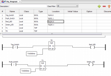
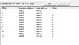
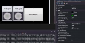
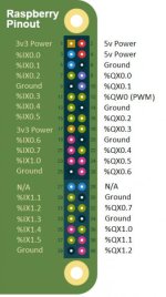
So attached are my screenshots.
The pi has 2 pull up resistors so I don't know if that's the reason as Im not sure how to make a normally closed button in the HMI?

But I have used negated contacts in the ladder.

Any and all help appreciated.

ladder1.png modbusread.png hmi.jpg pi.jpg
 
You probably can't change the state of your physical inputs via HMI.

Instead, You can create local bools that don't tie to a location, and control those bits from the HMI.
You could then OR them w/ your physical inputs in your ladder.
 
The address on your HMI should be placed in the PLCAddressClick box I believe.

I would also look away from those registers (10000) and instead use 40000 range as according to the Modbus spec they are read only. Perhaps that is the issue?
 
Just to spell out your problem more explicitly, because it's a common trap for young players...

The way a PLC works (in general) is:
1. Read inputs
2. Execute code
3. Write outputs
Let's say you have a physical switch wired to "Input 0",and logic saying "if Input 0 is on, turn on Output 0".

Let's say you turn the physical switch on while the PLC is in the middle of step 2: execute code.

It will finish executing it's code, based on the status of Input 0 at the time it last read the inputs, which was zero. At the end of this scan, it will write the outputs. Since it executed the logic with the input off, it would have set the output off also, and so will turn/keep the output OFF.

Then it returns to step 1: read inputs. It now registers Input 0 as being on.

Next, it executes the code, which internally sets Output 0 to be on. Note that the output itself is not yet on - just the PLC's internal memory for Output 0.

Finally, it updates the outputs - so now it turns on Output 0.

Now, let's say that you have Advanced HMI set up with a switch that, when you click it, will tell the PLC to turn on Input 0. NOTE: Advanced HMI only does this once. When you click the switch to toggle it from off to on, it will send a single message to the PLC saying "set bit such-and-such to ON". Then it will sit there idle until you click the control again to turn the switch off, at which point it will send a single message to the PLC saying "set bit such-and-such to OFF".

So, AdvancedHMI sends a message to the PLC saying "turn Input 0 on". The PLC complies. Let's say that this message arrives before the part of the logic that deals with turning on this lamp. Having had Input 0 turned on by Advanced HMI, it will update it's output image with Output 0 in the ON state, and then when it gets to step 3, it will turn on output 1. But then...

Back to step 1: read inputs. The PLC reads the physical inputs, and notes that Input 0 is OFF. It then executes the code, and seeing as Input 0 is OFF, turns Output 0 OFF.

So at most, your output will be on for one scan, which is not enough to actually even see it happen. And even that's only if you AdvancedHMI message comes in before the relevant logic is scanned during Step 2 - otherwise, it just won't come on at all.

The very short moral of this very long-winded explanation is: don't directly address Inputs and Outputs on a HMI. Always use separate, internal memory bits in the PLC for HMI controls and indicators.

So in your PLC, you would have something like this:
Code:
|     Physical_Input                      Physical_Output
|----------| |----------+----------------------(  )--|
|                       |
|       HMI_Switch      |                  HMI_Indicator
|----------| |----------+----------------------(  )--|
|
Hope that helps!
 
Thank you all for your replies.

I have this working now the way I want to however i know based on your comments this is probably not the best way to do it.

I'm doing a couple of online courses but for me just watching videos is not enough as I like to see things in action, but I can't really afford the cost of a full time on site course (or the time off work) or buying a 'real' PLC.

I'll post my logic up later and my HMI screen so you can have a look but be gentle (y)

Thank you all for your comments and I will post later on.

Ryan
 
Greetings,

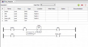
So attached is my ladder.

All it does at the moment is turn on a relay attached to the pi (and an LED) this in turn runs a very small fan for a short period.

It seems to be working at the moment but I'm sure there is a better way I should have done it based on your replies.

Thanks for looking and commenting.

Ryan

@Dravik - you were indeed correct I was trying to turn on a read only!!

fanladder.png fanred.png fangreen.png
 
Last edited:

Similar Topics

I'm fairly new to Rockwell software, I've had some basic training in the past but nothing too advanced. My company and I use Reliable products for...
Replies
0
Views
13
Hi all I need help on this As in my project used Schneider TM241 controller. Now I want to communicate Elite energy meter with controller by...
Replies
3
Views
79
Hi all, I am having issues accessing my Cimplicity software - the site code changed after re-install and I am no longer able to attain a new key...
Replies
10
Views
108
Good day all! Can someone help me with the procedure to update Beijers E700 firmware? The Panel I am working on is firmware 2.04v and I would...
Replies
1
Views
50
Hi, We have an application that has a device that goes through a reboot (appears un-graceful) What then happens is the MVI module appears to hang...
Replies
0
Views
58
Back
Top Bottom