Flow Rate and Flow Totalizer in RSLogix 5000

nur11

Member
Join Date
May 2018
Location
Texas
Posts
9
Hello. I wanted to write the logic of the flow totalizer and the flow itself for self-education in RSLogix5000 V20.01 software. After reading the literature, I realized that I do not know how to do this. The question is as follows
-I count the number of pulses per scan for example 1 sec
-How to remember the value of the number of pulses for the past scan?
- in order to calculate the difference and multiplied by the impulse weight to find the flow rate
-I do everything in LAD
Sorry for my english, thank you all
 
You have to use a counter (UP).
I´ll give you and example, first program your flowmeter to send a pulse each 100 liters for instance.
So everytime a pulse is sent from flowmeter to your PLC you have count 100 liters, so just multiply your accumulator number on your counter times 100 liters and you have all the water measured by you flow meter.
 
How frequent are you receiving pulses from the flow meter? You may need a special input card to receive pulses if they are too quick for a regular digital input card.

I would recommend an event task. You can configure the event task to run if a value updates from an IO card. It's pretty easy to do in PointIO, not sure in other Rockwell hardware systems. The benefit of an event task is it'll capture the pulses more reliably than a periodic task and you don't have to put in a high speed continuous task (not recommended by Rockwell).

In the event task, you should have a CTU that executes every time the event task runs if the pulse input bit is high. If you want to reset the counter, put a RES instruction on the counter outside the event task (you could also do a first scan clear here too). In the event task, you should have a MUL instruction that multiplies the .ACC of the counter by the volume each pulse represents. For example, if the .ACC of the counter is 146 and each pulse represents 100 liters, you multiple these two values together to get 14600 liters.

If you are receiving pulses very quickly (faster than an appropriate RPI for a normal digital input card), you will need a high speed counter card. The one I have used is a 1734-VHSC. It is annoying to use though, so I would avoid them unless necessary.
 
Last edited:
More literature to read:

https://literature.rockwellautomation.com/idc/groups/literature/documents/pm/1756-pm005_-en-p.pdf#%5B%7B%22num%22%3A6152%2C%22gen%22%3A0%7D%2C%7B%22name%22%3A%22XYZ%22%7D%2C214%2C728%2C0%5D

https://literature.rockwellautomation.com/idc/groups/literature/documents/wp/logix-wp003_-en-p.pdf

https://literature.rockwellautomati.../documents/rm/1756-rm094_-en-p.pdf#G7.1060400

I would set up the Event Task to be triggered by the 0-to-1 transition of the pulse from the flow instrument. The code for the task would comprise one rung and one instruction: [ADD Flow_Totalizer_Pulses 1 Flow_Totalizer_Pulses], where Flow_Totalizer_Pulses is a UDINT. Everything else, e.g. scaling, resetting the total to 0, calculating rate, etc., would be in the continuous task (or perhaps in a timed interrupt task for the rate calculation).

I notice that the event task can be configured to execute even if no Change-Of-State (COS) events are received; with a few more instructions, that feature could be used to trigger the flow rate calculation to put a 0 or display some other value to highlight or alert operators to the situation.

You'll just have to be mindful about triggering on the rising edge versus rising and falling edge. Rising edge event triggering alone wont work with a CTU because a CTU needs a false scan between scans in which it executes in order to increment (it has a oneshot built in). Rising and falling edge wont work with a self-addition (ADD(Total,1,Total)) because it will double count.

I agree that only the counter should be in the event task and all other functions (scaling and resetting) should be in a periodic or continuous task. Even though this is not strictly necessary (particularly in scaling's case) it would be easier to troubleshoot when as little code is in the event task as possible.
 
Thanks for the advice
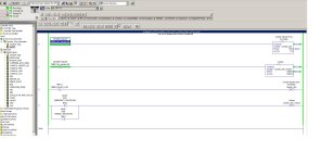
Do as you recommend. In this example, I just calculated the flow rate totalizer, but I don’t know how to calculate the flow rate because I don’t know the time for which the calculation is taking place? Appendix 1.2

Thanks for the advice
Do as you recommend. In this example, I just calculated the flow rate totalizer, but I don’t know how to calculate the flow rate because I don’t know the time for which the calculation is taking place? Appendix 1.2

Is it possible to calculate the counting of impulses for a certain amount of time?
For example 1 second:
-Counting pulses in 1 second only I don’t know how to save pulse data in 1 second
-Calculate the consumption
- Only the readings are very different
Appendix 3.4
Am I doing everything right?

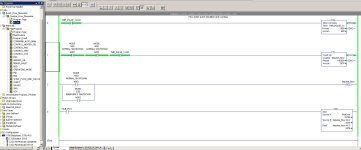
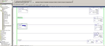
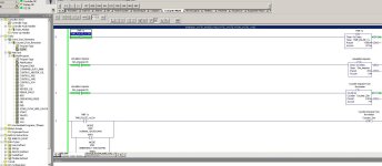
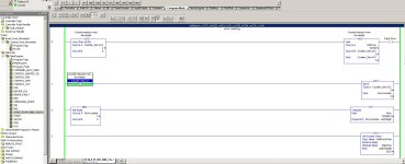
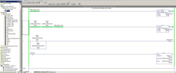
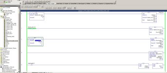
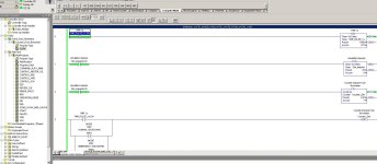
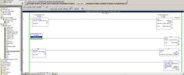
1.JPG 2.JPG 3.JPG 4.JPG
 
Thanks for the advice
I do what you recommend.
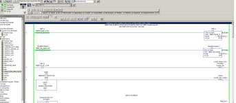
In this example, I just calculated the flow totalizer, but I don’t know how to calculate the flow because I don’t know the time for which the calculation is performed? Appendix 1.2

Is it possible to calculate the number of pulses in a certain time?
For example, in 1 second:
-Counting the number of impulses in only 1 second
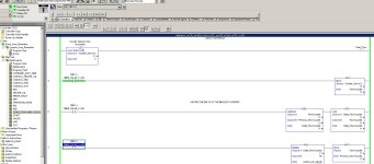
Appendix 3
-According to the formula, I calculate the consumption
- Only the readings are very different
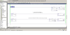
Appendix 4
Am I doing everything right?

Can calculate the number of pulses per second to save the value (just how to do it, I don’t know yet)
then subtract with the next value and then manipulate this difference to calculate the flow rate ?

1.JPG 2.JPG 3.JPG 4.JPG
 
Thanks for the advice
I do what you recommend.
In this example, I just calculated the flow totalizer, but I don’t know how to calculate the flow because I don’t know the time for which the calculation is performed? Appendix 1.2


Is it possible to calculate the number of pulses in a certain time?
For example, in 1 second:
-Counting the number of impulses in only 1 second
Appendix 3


-According to the formula, I calculate the consumption
- Only the readings are very different
Appendix 4
Am I doing everything right?


Can calculate the number of pulses per second to save the value (just how to do it, I don’t know yet)
then subtract with the next value and then manipulate this difference to calculate the flow rate ?

1)In this case your pulse is every second, so you have 3600 pulses per hour, an each pulse weighs 100 so your flow is 3600 times 100 (gals, liters, etc) per hour.

2) yes you can do it , but the bigger the lapse time you use the better the accuracy.

3) It seems like a homework.

4) No, Because you pulse is every second.
 
  1. Thanks for showing your code
    1. I am a little confused by the images you posted: 1.JPG and 3.JPG appear to should the same routine [FLOW].
    2. I see you are running this on an emulator; because this is an emulator, you will not be able to use an an Event Task triggered by a Change-Of-State (COS) of an input pulse, or at least if you create one you may have no way to automatically trigger it, in the emulator, to ever run.
    3. So you are trying to generate a simulated flowmeter pulse; that timer should probably be in the continuous task.
      1. The Event Task needs but one rung, and that rung should EITHER
        1. feed a counter (CTU instruction) with [XIC Input_Pulse] if both 0-to-1 and 1-to-0 Change-Of-States (COS) trigger the Event Task,
        2. OR use an ADD instruction to increment a pulse counter tag if only the 0-to-1 COS triggers the event task.
  2. You need to add comments to your code to make it easier to follow; that may not seem to matter now, but that is only because you current have all of the expected functionality in your head; it will be important when you come back to this code in a few months without that knowledge.
  3. The .ACC accumulator of a counter structure is a DINT (twos-complement i.e. signed 32-bit integer; see this link), so ADDing 32768 is going to take many (~131000) scans to get the .ACC value out of negative territory after it rolls over.
  4. I think you already know this, but in order to calculate rate from a counter that is accumulating, you need two accumulated values (accumulate pulse counts or accumulate volume) separated by a known time.
    1. So each time the timer expires, i.e. on each single scan when .DN is 1, the code will
      1. calculate the the accumulated volume, tag [Volume]
        1. N.B. although it looks like you are already doing this on every scan already in the MUL instruction on Rung 2 of program [SCALE_FLOW_AND_CALC...], so you do not have to do it again
      2. Calculate the rate, volume per second, by subtracting the value in tag [Previous_Volume] from the current value in tag [Volume], and put the result in tag [Volume_Rate], then divide [Volume_Rate] by the [timer preset converted to seconds].
        1. See the next item to understand where [Previous_Volume] comes from.
        2. You may have to do some fancy dancing to deal with counter rollover.
      3. MOVe the current accumulated volume, tag [Volume], for the next time .DN is 1
        1. to do this, you will need to create a floating-point (REAL) tag, call it something like Previous_Volume, and initialize it to 0
        2. Note that it is necessary to execute the MOVe into [Previous_Volume] tag after calculating the rate.
    2. It may be better to do the subtraction using the .ACC DINT value because of the rollover issue to get the counts per second, and then scale the that counts/s difference to Volume/s.
    3. N.B. there is a small inaccuracy here because the [XIO ....DN TON ... 1000 0] logic actually runs a little longer than 1s, so the actual time between consecutive volume rate calculations is something like 1.001s or more.
  5. FYI: DateTime[0].31 (2.JPG, [SCALE_FLOW_AND_CALC...] routine, Rung 4) is not going to be 1 for over two billion years.
 
See the next item to understand where [Previous_Volume] comes from.
You may have to do some fancy dancing to deal with counter rollover.
MOVe the current accumulated volume, tag [Volume], for the next time .DN is 1
to do this, you will need to create a floating-point (REAL) tag, call it something like Previous_Volume, and initialize it to 0
Note that it is necessary to execute the MOVe into [Previous_Volume] tag after calculating the rate.
I DID NOT UNDERSTAND THIS METHOD
CAN CALCULATE EXPENDITURE PERFORM
-Adding the number of pulses multiplied by the weight of the pulse?
KINDLY TAKED INTO ACCOUNT ALL YOUR REMARK
APPENDIX 1,2,3,4
It seems that I took into account all your comments.
APPENDIX 1,2,3,4
Can you comment on my mistakes
Thanks for the video, only I could not repeat the project at home

1.JPG 2.JPG 3.JPG 4.JPG
 
  1. ...
  2. You need to add comments to your code to make it easier to follow; that may not seem to matter now, but that is only because you current have all of the expected functionality in your head; it will be important when you come back to this code in a few months without that knowledge.
  3. ...


This is very important; see this link. Write a detailed description on every rung of what you expect and want that rung to tell the PLC do. Then, you can analyze the rung and see what that rung actually tells the PLC to do. Because the PLC is not interested in what you want it to do, but it will always do exactly what you tell it to do.

I have posted this several times.
For any given homework assignment or task at work, you must consider these instructions as the customers specifications.
1. read the specifications several times.
2. write down your understanding of what you read in a step by step fashion.
3. review what you wrote down and see if it makes since, modify if necessary.
4. Get with the mechanical designer and discuss the project openly and honestly. When your opinions differ in regards to an operation, discuss it, don't ignore it.
there must be a reason for a difference of opinion. modify your instructions and i/o to accommodate the mechanical design if possible. Mechanical design may have to be changed due to plc programming limitations.
YOU BOTH MUST be in agreement on all points of operation before going to step 5. you may have to modify/rewrite step 2 and 3 based on the discussion.
5. step through your notes again this time, you are the one following the instructions. In other words, you are the plc. Write down on paper the events you are doing.
For example, turn on hydraulic motor 1, write down hydraulic motor 1 on. If a sensor is needed, write that down.
6. continue through the instructions. When you turn off the motor, mark a line thru it.
7. go through your instructions with all the sensors, motor aux. contacts, outputs documented. Modify if necessary.
8. repeat step 6 until no changes are made.
9. Try to group your data words into some organized fashion. The more programs you write, the more organized you become
10. write the plc program using your notes in a step by step manner.
10A Over half way through writing the program you WILL realize a different/better way of doing something you are almost done writing
(or a new spec will require it) and you will completely rewrite it
10B It WILL happen more than once.
Note: 10A and 10B added to list. thanks Aabeck, member plctalk.net forum


11. DOCUMENT EVERYTHING!!! You may remember things today, but in 5 years and hundreds of programs later, you won't
remember, especially at 2 am, so DOCUMENT EVERYTHING. use easy to understand tags and rung comments.
12. MAINTENANCE is your best friend and your worst enemy.
if you work with them and find out what they can do, write the program where they can trouble shoot the program. they will be able to fix the problem and everyone will be happy.
BUT
if you write the program to where you are the only one who understands what is going on, maintenance can't fix the issue, the machine is down, production is down,
management hears about it, your boss hears about it, then you hear about it - rewrite the program or else. you get calls all hours of the day and night.
this still holds true, a machine can cost a billion dollars, but it's not worth 10 cents if maintenance cannot trouble shoot the issue and fix the issue.
everyone has their own style of programming and you must develop your own way as well.
13. when the customer is in your shop and brings maintenance, discuss things with them, let them see your code, be open.
if they make suggestions, write them down, don't ignore them. their ideas may save you days of programming.
14. install the program and leave in program mode if possible so you can to debug your i/o
15. when writing your instruction manual(s), use your notes from step 9. Use easy to understand English language. specify the i/o, timers, counters, outputs when possible.
this will help maintenance even more to see what is going on.
16. Question for you, when is a machine and plc the most dangerous and why?
When it’s first powered on – when power is first applied to a machine, you don’t know how things are wired.
When you energize the plc outputs, you don’t know how they are wired.
When the plc is put into run mode the first time, it will do what you told it to do, NOT what you wanted it to do.


17. debug the program.
Remember, the program will always do what you told it to do, NOT what you wanted it to do.
18. IF you can ask a what if this happens type of question, YOU MUST have an answer, EVEN IF its a 1 in a million chance. that what if situation will happen in the first 30 minutes of production runoff in front of the customer.
regards,
james
 
Thanks for the video, only I could not repeat the project at home

Fix this before you fix anything else.

Can you comment on my mistakes

Yes ;).

But it would be better if you find them yourself via Rubber Duck Debugging.

Do you understand how a PLC works? Watch Ron Beaufort's series of videos at this link.

  1. What is the process that the PLC is trying to model?
    1. What inputs are coming from the process to the PLC?
      1. What kind (analog, discrete, etc.) are each of those inputs?
      2. What are the engineering units of each input?
    2. Use as much detail as possible.
    3. Write down any formulae involved.
    4. What is the purpose of the counter simulators?
      1. Are they simulating a part or parts of the process that you do not have connected to the PLC at this point, so you can develop the rest of the program?
        1. What part or parts of the process are the each of counter simulators simulating?
        2. How accurately do they simulate that part of the process?
        3. What is the meaning of the TIMER_1s.DN bit i.e. what part of the process is it simulating in the [FLOW] routine?
        4. What is the meaning of the TIMER_Sim_Impulse bit, i.e. what part of the process is it simulating in the [FLOW] routine?
      2. Do the .PREset values of the counters have any meaning?
  2. What is the purpose of the [FLOW] routine?
  3. Why does the [FLOW] routine appear to be set up as an Event Task?
      1. What causes the [FLOW] routine to be executed?
        1. How often does this happen?
        2. What is the purpose of an Event Task?
  4. What causes the [SCALE_FLOW_AND_CALC...] routine to be executed?
  5. Why are there two counters in the [FLOW] routine, being triggered by the same logic?
    1. Write down the forumulae explaining how the Counter_Sim.ACC and Counter_Sim_Volume.ACC tags are related to the flowrate and the accumulated flow.
  6. Why does Rung 3 of the [FLOW] routine duplicate Rung 3 of the [SCALE_FLOW_AND_CALC...] routine?
    1. Are both really necessary?
  7. May we assume that the [FLOW] routine is an Event Task and is not executed every time or as often as the [SCALE_FLOW_AND_CALC...] routine?
    1. From Rungs 0 and 1 of the [SCALE_FLOW_AND_CALC...] routine, we can see that the TIMER_1s.DN and TIMER_Sim_Impulse.DN bits (Booleans) will each be 1 for at most one scan in the continuous process, but the [FLOW] routine uses those bits to set the stat of the input rungs to counters in the [FLOW] routine, which means the counters only react to 0-to-1 or 1-to-0 transitions of those bits, which in turn necessitates that the [FLOW] routine be executed during or between the continuous scans when the [SCALE_FLOW_AND_CALC...] routine assigns a 1 to those bits, so how have you ensured that those transitions are detected by the [FLOW] routine, or is it perhaps not important that every transition is detected?
    2. The .DN bits of the timers will have values of 0 for most of the time and a value of 1 for a very short time, so why do you use the XIO instruction on the timers' .DN bits to to set the state of the input rung to the counters, instead of using the XIC instruction?
  8. How does my logic to calculate the delta_count from counter .ACC and last_count values work?
    1. What is integer rollover?
      1. What is the range of values that can be represented by DINT tags?
        1. What happens to the counter structure's .ACC, when its value is the maximum value in that range, and the counter detects a rising edge (0-to-1 transition) of its input rung?
    2. Why did I use two branches with OTU and OTL instructions instead of a single OTE instruction to assign a value to bit 31 of last_count?
  9. Why do you reset the Counter_Sim counter structure every second, on Rung 2 of the [SCALE_FLOW_AND_CALC...] routine?
    1. Is this why you ADD the FlowCounter value to the Delta_FlowCounter in the third instruction of Rung 6 of the [SCALE_FLOW_AND_CALC...] routine?
    2. Does your bookkeeping lose a flowmeter pulse that might occur since the previous scan, when the Counter_Sim.ACC value was MOVed to FlowCounter?
      1. Won't that pulse be lost by the RESet?
I could go on (and on and on), but this code needs to much more simple than it is. I suggest you start over and refactor, starting with @James Mcquade's list (cf. my previous post), where you will spend over half a dozen steps understanding the process before you write even one rung of code.

You are a beginner, and that is fine and that is not a criticism, because we were all there once; what is important and encouraging is that you are asking questions. But I think the crucial thing that you do not yet understand is that a PLC program, or any computer program, is a model of something in the real world. That means you will need to define your model first; only after that should you write the code to implements that model.

Furthermore, as you write every line of code it should be checked against the model, to ensure it is implementing the model correctly. For difficult parts, write small, temporary test programs, completely separate from the final code, that will help you to understand how individual instructions (timers, counters, etc.) and other PLC entities (event tasks, continuous tasks, etc.) work.

Bottom line: if you cannot describe the process, you cannot design a model of the process; if you cannot design a model of the process, you cannot code an implementation of that model.
 
Last edited:

Similar Topics

Hi, The hardware is: Click Plc model # CO-O1DD1-O HMI model # S3ML-R magnetic-inductive flow meter model # FMM100-1001. I will set the flow meter...
Replies
4
Views
115
One of the engineers has asked me to add code to the PLC to calculate oil flow rate based on delta pressure, using the equation below: Flow rate...
Replies
13
Views
2,781
can any one help with the math for converting an instantaneous value to a totalised value for Gas Consumption usage every hour. in the plant we...
Replies
5
Views
3,177
Hi, I have AB PLC (1769-L30ER) and PV800 HMI in my project. I have a horizontal tank (same dimension) having a height of 200" and capacity of...
Replies
1
Views
2,060
i need to Totalise an instantaneous Flow rate in scada. i will probably use the scada totalise function, just want to know if this code concept is...
Replies
2
Views
1,298
Back
Top Bottom