AutomationTechBrian
Lifetime Supporting Member
I was called to help a customer setup a Mitsubishi Servo Drive to a Micrologix 1400. No fieldbus is used, the positioning program is controlled with discrete PLC outputs, with an analog pot for torque limits.
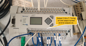
When I got there, the customer had all of the required Drive I/O already wired to random outputs on the Micrologix PLC for a test application. For simplicity, a bunch of them were originally wired to outputs 2 thru 7, which all used the same 24vdc source. He had a test ladder set up to toggle bits tied to the Local outputs. But when he toggled one of the bits, several of the outputs turned on. They didn't show up as being on in the PLC display, or in the online RS Logix, but the Servo Drive showed them as being on. I grabbed my meter and found that the non-activated outputs had 14 vdc... which is evidently enough to be considered "on". I moved several of the wires from outputs 2-7, to other outputs (see pic), and this fixed the problem. We got the Servo test program to work, but now tomorrow we'll look at permanent wiring.
I suspect you guys have seen this before. Is this indicative of a bad PLC, or is there something we're missing in the wiring? I was focused on the servo programming until the end of the day, when we figured out there was a PLC issue. I took this picture just before we left for the day. I noticed that there is a "COM2" or common terminal for that group of outputs. There was nothing wired to it because he said an "example" PLC did not utilize the "COM2" terminal. Is that the issue?
I'm hoping to learn something about this before tomorrow morning. Let me know what you think, please.

Last edited:


