Controllogix PID Bumpless Transfer

Mattyweb1990

Member
Join Date
Feb 2014
Location
Scunthorpe
Posts
7
Morning all,

Could anyone shed some light on whats happening with my PID Loop?

On our plant we have a 'fast ramp' on the PID Instruction done in .SWM which essentially adds 8% every second to .SO until it reaches specific value in either the .SO or the Process variable.

The issue is that when we change over to Auto when the above conditions are met - we'd expect to see a bumpless transfer but we don't.

Example

Switched from .SWM to Auto at 70% .SO

Error still Positive - .SO Goes to 68%

Next UPD

Error Still positive but reduced - .SO goes to 67%

This goes on until the Loop is back in control.

It appears to me the KP is causing this but i would of thought the 70% .SO would of been purely a back calculation of the integral so a reduction in Error shouldn't reduce the .SO?

Any thoughts?

Heres the Independent Constants - KP - 0.644 KI - 0.097 KD - 0 (Bumpless transfer is enabled!)

Cheers!
 
Using Set Output (.SO) in Software Manual (.SWM) is an appropriate way to do what you are describing in open-loop control. The consequence is that you have error between Set Point (.SP) and the Process Variable (.PV) when closing the loop at the end of the output ramp (i.e., when unlatching .SWM).

You have two options to eliminate this error-induced bump:

1. Eliminate the closed-loop error by (a) one-shot moving PV into SP when unlatching software manual, or (b) enable Process Variable Tracking (.PVT), which causes the loop to set SP to PV at every update while in SWM. After switching to auto, you may need logic to move the desired set point in SP, which will likely cause control action due to SP/PV error.

2. Instead of ramping output (SO) in manual, consider ramping set point (SP) in auto. This might be a better option, especially if there is a target SP after ramping, as opposed to just holding the PV at its current value at the end of open-loop, SO ramping.
 
...
It appears to me the KP is causing this but i would of thought the 70% .SO would of been purely a back calculation of the integral so a reduction in Error shouldn't reduce the .SO?

I also want to add that this is a correct interpretation of the "bumpless transfer" with respect to the controller output: on the PID scan when the loop transitions from manual to auto, the SO value is moved into the integral term (when I gain is non-zero) as a starting point for the loop. This is a why it is important to send manual control action through the PID loop rather than bypassing the loop and directly manipulating the final control element (e.g., analog output to a valve).

However, as described in the previous post, any SP - PV error at the manual/auto transition will cause the proportional action to change this starting point value (e.g., 70% to 68%) . Subsequent PID updates will include integral and derivative action as well.
 
...You have two options to eliminate this error-induced bump:

Another option to consider if the output ramp rate (8%/sec) and PV target are important, but the ramp time is flexible: stop the output (SO) ramp and switch to auto at the time when PV exceeds target (SP). In other words, monitor the target SP minus PV error while ramping, and unlatch SWM when it goes negative (or is less than a "pre-act" value).

This will likely reduce the overshoot implied in the original post, and might be a relatively easy logic change.
 
Last edited:
However, as described in the previous post, any SP - PV error at the manual/auto transition will cause the proportional action to change this starting point value (e.g., 70% to 68%) . Subsequent PID updates will include integral and derivative action as well.

This part confuses me. There will always be some SP-PV error when switching back to auto, so I thought the whole point of bumpless transfer was to back-calculate the integral value to the exact amount to offset the proportional action. Why would there be any proportional action left if this was done properly? :confused:
 
This part confuses me. There will always be some SP-PV error when switching back to auto, so I thought the whole point of bumpless transfer was to back-calculate the integral value to the exact amount to offset the proportional action. Why would there be any proportional action left if this was done properly? :confused:

This is an important question, and I will try to answer using some theory and a couple examples.

The theory part goes to the "positional" form of the PID equation in the Allen-Bradley PID instruction. (This does not apply to the PIDE instruction which implements the "velocity" form.) At each scan of the PID, it conceptually computes the controller output in Auto mode as follows:

Error = Set Point - Process Variable
Output = P-Gain * Error + I-Gain * Acc. Error + D-Gain * Error ROC + Bias

Acc. Error is accumulated error since the loop went to Auto.
ROC is error Rate-of-Change.

This is the "independent" gain form, and leaves out some details not directly relevant to this discussion. I will just add that "positional/velocity" form and "independent/dependent(ISA)" form are separate topics, creating four different expressions: PID-Ind, PID-Dep, PIDE-Ind, PIDE-Dep.

For the following examples consider a temperature control application, such as an oven, where increasing the controller output adds heat and raises the measured temperature. The target, Set Point, temperature is 100 degrees.

Example #1: The loop is in manual and the operator adjusts the heater to get the oven temperature right at 100 degrees before switching the loop to auto. Let's say this manual adjustment is 70%. If there is no "bumpless" compensation, the initial PID output is conceptually computed as:

Error = Set Point - Process Variable = 100 - 100 = 0
Output = P-Gain * 0 + I-Gain * 0 + D-Gain * 0 + Bias = Bias

If there is no Bias, the output suddenly goes from 70% to zero because there is no error, acc. error, or error ROC. The oven will then start to cool, which causing the output to increase. Eventually the output will work its way back to where the operator maually adjusted it, 70%, assuming no process disturbance during the recovery and stable tuning. However, there will be a temperature "bump" due to the output going to zero.

Fix #1: Make all manual output adjustments through the PID instruction so it "knows" the heater setting when the loop goes from manual to auto. Use this knowledge to start out in auto at this output, and avoid the temperature "bump" caused by the output going to zero and then working its way back to the starting point. The AB PID instruction does this by calculating an accumulated error to make the integral contribution equal to the output at the manual-to-auto transition. (If I-Gain is zero, it will use the Bias value if enabled.) Using the 70% manual output, zero Error, and zero Bias:

Error = Set Point - Process Variable = 100 - 100 = 0
Output = P-Gain * 0 + I-Gain * (70/I-Gain) + D-Gain * 0 + 0 = 70

In this situation, the output stays at 70% after the careful manual adjustment, and there is no "bump."

Example #2: The loop is in manual and the operator adjusts the heater using the loop's Set Output, but only gets to 90 degrees before switching the loop to auto. Let's say this manual adjustment is 65%. With "bumpless" compensation, the initial PID output is conceptually computed as:

Error = Set Point - Process Variable = 100 - 90 = 10
Output = P-Gain * 10 + I-Gain * [(65/I-Gain) + 10] + D-Gain * 0 + 0 = P*10 + 65 + I*10

(Note: For AB-PID, this example assumes an engineering unit scaling of 0 to 100 degrees = 0 to 100 percent full scale. Important, but not to this discussion.)

So the output will start with the 65% from the manual starting point plus some additional action because of the non-zero error going into the P and I terms. This control action will continue to increase ("bump") the output from its starting point (65%) until the error goes to zero.

Fix #2: Force the error to zero at the manual-to-auto transition. This can be done with an AB-PID feature called Process Variable Tracking (PVT), which moves the Process Variable value into the Set Point at every loop update while in manual. It is also possible to do this with a one-time move in logic when triggering the manual-to-auto transition.

However, this "fix" may change the Set Point to something other than the desired target. In the case of Example #2, the Set Point becomes 90 degrees instead of the desired 100 degrees. It would then be necessary to increase the Set Point to 100, thus increasing the output. So, with this fix there will eventually be a "bump" unless the output is carefully adjusted in manual to have zero error, as was the case with Example #1.

PVT is most useful when the loop set point is allowed to float, such as with the inner loop of a cascade arrangement.

This explanation got a bit longer than expected. Hopefully the examples help to understand the PID behavior at the manual-to-auto transition.
 
I haven't seen rate of change of error defined but the OP. My guess is this is simply a response to the physical rate of change of error relative to the integral rate. Two statements from the OP kind of lead me this way. The first is:

Originally posted by Mattyweb1990:

Error still Positive - .SO Goes to 68%

Next UPD

Error Still positive but reduced - .SO goes to 67%

The second is:
Originally posted by Mattyweb1990:

...so a reduction in Error shouldn't reduce the .SO?

The first quote indicates that the error is positive (setpoint greater than actual) but the output is decreasing. The second quote indicates the magnitude of the error is decreasing.

This simply means that the error/proportional gain product is decreasing faster than the error/integral gain sum is accumulating. Add into that the presence of a derivative term, which will be further decreasing the output in an attempt to stabilize the process variable, and it is quite possible that the output would decrease even though the error is still positive.

Bumpless transfer will only calculate an output for the moment in time that the transfer from manual to auto occurs. It isn't fully model based so the bumpless transfer process can't account for system dynamics at the point of transfer or into the future. It may not be able to in any case. If the error rate is faster than the current gain structure can support there really isn't much the PID equation can do to smoothly transition into auto control with little or no change to the output. Ultimately the loop need to take control of the process and regulate it based on the gain structure at that time.

As Mispeld said, if you really don't want the CO to change after a bumpless transfer your best bet may be to use Process Variable Tracking. But even that won't behave as you expect unless the system is at steady state before the transfer. If the error rate is significant at the time of transfer there isn't much you can do to make things different.

Keith
 
Appreciate everyone's help - I hope you all had a great Christmas!

I think I'm going to go with the approach you mentioned having the Loop in PV Tracking whilst in SWM.

But because I'm dealing with Oxygen flow I may at first want to try the approach also mentioned above where to leave the Loop in SWM until its reached SP OR Reaches a predetermined time (In case in SWM never reaches SP as it relies on the Plant O2 Pressure at the time it demands O2 Flow).


I know this will fix the issues but i'm still finding it hard understanding why the loop reduces output when the error is still positive. Surely if it was going to bump it would increase the output?

It's almost like its calculated the KP Gain earlier in SWM and as the Loop has naturally reduced the error (Still in SWM) and as the Loop goes into Auto the KP Gain has reduced and pulled the Output back.


Maybe that's why others call it Anti-Integral windup... Only stops the Integral windup but can't control what the KP Gain does!
 
This simply means that the error/proportional gain product is decreasing faster than the error/integral gain sum is accumulating. Add into that the presence of a derivative term, which will be further decreasing the output in an attempt to stabilize the process variable, and it is quite possible that the output would decrease even though the error is still positive.

Bumpless transfer will only calculate an output for the moment in time that the transfer from manual to auto occurs. It isn't fully model based so the bumpless transfer process can't account for system dynamics at the point of transfer or into the future. It may not be able to in any case. If the error rate is faster than the current gain structure can support there really isn't much the PID equation can do to smoothly transition into auto control with little or no change to the output. Ultimately the loop need to take control of the process and regulate it based on the gain structure at that time.

As Mispeld said, if you really don't want the CO to change after a bumpless transfer your best bet may be to use Process Variable Tracking. But even that won't behave as you expect unless the system is at steady state before the transfer. If the error rate is significant at the time of transfer there isn't much you can do to make things different.

Keith

This would make sense to me if I saw the output go from 70% to 72% Then back to 70% due to the integral not overcoming the KP.
 
But why would it necessarily have to go up first? If the error is decreasing faster than the integral is allowed to increase the first step after the transfer would be a decrease in output.

For this example we will ignore the derivative contribution because that will just make the results worse. Assume that with a 70% manual output the process error is decreasing at the rate of 1%/second and you switch to auto when the error is at 5%. Further assume you have proportional gain of 1% output / % error and you have an integral gain of 0.1% output / % error/second. Further assume the loop update time is 1 second.

At the point of switching you will end up that a 5% proportional contribution and a 65% integral sum. If the process were perfectly stable at the time of switching these numbers would remain unchanged for the foreseeable future. but the process is not stable. The error is decreasing at the rate of 1%/sec with a 70% output. So the loop update after the switch will result in an error of 4% (error decreasing at 1%/sec and loop iteration is 1 sec), a proportional contribution of 4% and an integral contribution of 65.4% ( 65% + (0.1*4%)) for a net result of 69.4%, a decrease from the previous loop iteration. This will continue with decreasing effect until the error rate gets low enough that the integral contribution is changing the integral sum faster than the error rate.

Keith
 
Awesome Keith,

I just got caught up on the Rockwell literature abit too much as it states the .SO at the point of the manual to auto switch is a back calculation of just the integral term! So I just assumed at the point of Changeover the KP would of just been an addition onto the .SO

Thanks for taking the time to write that detailed reply!
 
Switched from .SWM to Auto at 70% .SO

Error still Positive - .SO Goes to 68%

Next UPD

Error Still positive but reduced - .SO goes to 67%

...

Heres the Independent Constants - KP - 0.644 KI - 0.097 KD - 0 (Bumpless transfer is enabled!)

When I first read this I was incorrectly interpreting "Error still Positive" as "process variable overshot set point." Overshoot would be a change from positive to negative error, and is necessary to cause the incremental reduction in PI controller output described. Specifically, if manual loop output is 70% at the auto-to-manual transition, error must be negative for it go to 68%, 67%, ... with only Proportional and Integral action.

One way to explain the positive error situation is that Set Output is not actually 70% when the loop changes from manual to auto. For example, if the logic is written such that first PID update after the .SO changes from, say, 62% to 70% is the same PID scan that .SWM goes from 1 to 0, I'm pretty sure the bumpless back-calculation will use 62%, and not 70% (i.e., the auto transition takes precedence over the .SO change). In that case, positive error initially increases 62% to 68%, and then starts backing off to 67% as the PV approaches set point.

In order to start the loop at 70%, make sure it is scanned in SWM with the SO at 70%, and then unlatch SWM for the next PID update.

This timing will be less significant if the logic is changed to trigger the manual-to-auto transition based on monitoring SP - PV error during the ramp period, rather than at a fixed percent output. In that case, the PID behavior described, if true, might be desirable if the ramp calculation is synchronized with the PID scanning.
 
Nope, goes out of SWM when the .SO Equals 70%.. Ive trended and exported the data to Excel to double check. All the periodic timing is done correctly - Keith seems to be correct but like I said before.. Rockwells definition of bumpless transfer and mine go against what's actually happening.
 
...For example, if the logic is written such that first PID update after the .SO changes from, say, 62% to 70% is the same PID scan that .SWM goes from 1 to 0, I'm pretty sure the bumpless back-calculation will use 62%, and not 70% (i.e., the auto transition takes precedence over the .SO change)...

As a follow-up to this explanation, I wrote a short program to determine how a simultaneous change to .SO and .SWM is handled. Test results indicate clearing .SWM does "take precedence" over a change to .SO on the same PID scan (with rung-in true) -- in that the accumulated integral term is initialized by the .OUT value from the previous scan (i.e., the last .SO when PID was scanned with .SWM set), rather than the current .SO value.

In other words: the PID must be scanned in SWM in order to move .SO to .OUT, and .OUT is used for bumpless transfer to Auto.

Since .SO is typically set when going from Auto to Manual, this situation is not usually a concern. It would only come into play when, for example, a programmed change in the .SO triggers the unlatching of .SWM.

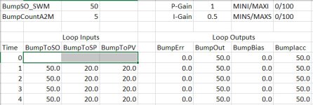
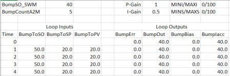
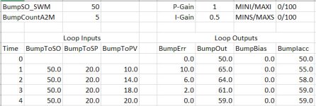
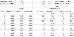
Attachments include four bumpless transfer tests:
1. No change to SO, SP equals PV
2. SO change at SWM clear, SP equals PV
3. No change to SO, PV below SP, increases to SP
4. No change to SO, PV below SP, output to 100%

Test #4 demonstrates anti-windup feature of the Logix PID instruction.

Code is attached, and can be helpful in understanding how various input conditions are handled when going from software manual to auto.

BumpT1-Baseline.jpg BumpT2-SONotChanged.jpg BumpT3-SPError.jpg BumpT4-AntiWindup.jpg
 

Attachments

  • BumpPIDLadder.pdf
    296.5 KB · Views: 43

Similar Topics

Hello, I have a PID that I am using for an oxygen valve that regulates the pressure. Often when the header pressure is too low, the output will...
Replies
4
Views
1,277
Hello all, I have a pump that has operational limits 15-100% Speed (9-60Hz). 1. On the PID instruction would you limit (.MINO=15% and...
Replies
21
Views
5,154
Why is my PID .PV (Process Variable) getting continually overwritten with some strange value every time the rung my PID Instruction is on goes...
Replies
4
Views
2,133
Hi there, I have a PID which I limit at MINO = 25% and MAXO = 100%. When the PID runs for the first time it takes time to start reacting at 25+%...
Replies
3
Views
3,062
Hey fellas, I'm in the midst of doing my first translation from 5 to 5000 that also includes PID instructions. I'm just looking for any helpful...
Replies
10
Views
5,441
Back
Top Bottom