Stumped

CJones

Member
Join Date
Aug 2007
Location
South Carolina
Posts
55
Not looking for the answer but pointed in the right direction.

I have one sensor wired to one input, as a large gear turns the sensor restes a timer which keeps an alarm off

If the timer runs out and the sensor has not seen it's "flag" it turns on a yellow light alarm

All is good

I want to use this same input to record RPM or in this case to scale and record the "HZ" that the drive is running.

I have tried a timer and RTO using the opposite intruction to move the number (in seconds)to a N:7 address, the only problem is it tends to reset before the move takes place?

For example if there was 15 seconds on the timer between flags I would like to move this 15 seconds and scale it out between 0 and 60 HZ.

Any takers

thanks in advance Clint

I'm using a 504 and we have to keep it simple I don't yet know how to bit shift unless you want to explain it
 
Last edited:
How about counting the gear teeth and doing some maths to come up with a speed value?
Or use a counter that increments and every time your sensor is made, the number or counts will be proportional to the speed of the gear.

I'm not an AB man so cannot really suggest how to do this in AB!
 
Last edited:
Just to keep you busy till the experts get here..... try making the reset a condition of the "move".

Or use a separate timer that doesn't get reset until everything has happened that you WANT to happen......

Just for a "direction"....

Stationmaster
 
What kind of sensor is this
micro switch that is tripped by the gear?
encoder? If you know pulses per revolution AND you can time it then you can derive RPM
Proximity detector counting teeth? Same basically Teeth per rev and derive it.

Dan Bentler
 
Last edited:
Not looking for the answer but pointed in the right direction.

I applaud your desire to learn!

What I do when I can't figure out something in the PLC is to take a step back and try to see how I would do it without the PLC.

Imagine you have your eyes, a piece of paper, a calculator and a stop watch. How would you figure out the Hz then? What steps would you take? What information do you need to keep track of and what formulas must you use to calculate the Hz?

Once you go through this type of exercise, you truly understand the task and can then find the tools available in the PLC to replicate your process.
 
HI CJ

Use the done bit to activate the move to command.

Test Bit
------\\----------(TON)

TON done bit
------\\----------(MOV)

TON done bit
-------\\---------(RES)

Just an idea.
 
Clint,
I think I would separate the two tasks. The timer works great for your first task so keep it; however, depending on your pulses comming into the PLC you may not be able to accomplish the RPM with the same logic. If I was looking for steady state RPM, I think I would just take the pulses and count them. Then every x seconds calculate the RPM from the number of pulses counted. You may need to look at input interrupts to get an accurate count. Depending on the speed, you may need to use DC inputs, HSC inputs, etc. A lot depends on the processor you are using and hardware you have as to how to acomplish the task. Maybe this will give you a bump in the right direction.

Russell
 
Not looking for the answer but pointed in the right direction.

I have one sensor wired to one input, as a large gear turns the sensor restes a timer which keeps an alarm off

If the timer runs out and the sensor has not seen it's "flag" it turns on a yellow light alarm

All is good

I want to use this same input to record RPM or in this case to scale and record the "HZ" that the drive is running.

I have tried a timer and RTO using the opposite intruction to move the number (in seconds)to a N:7 address, the only problem is it tends to reset before the move takes place?

For example if there was 15 seconds on the timer between flags I would like to move this 15 seconds and scale it out between 0 and 60 HZ.

Any takers

thanks in advance Clint

I'm using a 504 and we have to keep it simple I don't yet know how to bit shift unless you want to explain it


I take it from your post, that N7:0 is always equal to zero. Is the reset before the mov statement? Do you use a one shot to move the value to the integer file? The sensor is on for more than one scan, it may move the file on the first scan, and then overwrite it the next, as the sensor is still on, and resetting the Timer. You'll never see this, with the update time of the GUI.

On a slow moving input like this, what you described should work fine. Set your time base as low as possible, and still keep the timeout value below 32,767. For faster inputs, I ussually count the number of pulses per time, for slower ones, I use time per pulse.

-MUR
 
All Good,

Ken, Leit

I'm stuck using what I have which is one 18mm AC two wire sensor that I'm already using for the alarm, there are four sensors on four gears that are approxametly 48 inches in diameter.

I would use the teeth on the gear and count teeth except for the fact that when the gear stops it could easily stop on a tooth keeping the timer from timing? So I made a "flag" (a piece of metal sticking out away from the gear teeth)to limit the likelyhood or the flag stopping over the sensor.

The times on the gear revolutions are 20 seconds for two of them 300 seconds for one of them and 10 for the last, so it's not really a pulse to be counted since running the gear at 60 HZ might mean a revolution of 10 seconds and running the same gear at 20 HZ might be a time of 30 seconds per revolution.

Patrick I have goofed around with every combonation of using the timer bits and it always resets before the move takes place, the TT and En always go at the same time and since the timer doesn't finish timing there is not DN bit to use. I had some results with an RTO but ended up with a confusing mess

Markie, I could handle that except on the 300 second one if I made the move every one minute I would get a bunch of zeros

PLC Mentor I'm competent enough (I think) to count teeth and come up with something, but I would have to pull wire purchase and mount another sensor, in this economy cheap is best, so I'm stuck with what I have.

Brijm, The input is only on for a very short time it is an 18mm sensor with a 1/2 inch flag so it's milli seconds just enough for a good signal to minimize the chance of the flag stopping over the sensor, which would make the alarm ineffective.

Ndz, I'm looking

Thanks all something will hit

Clint
 
I would still try to count the teeth on the gears. You might find a 3 wire sensor operates faster though.

You could move the counter value to a data word on the leading edge of the "Flag" input. In the next network, reset the counter. Perhaps you would need some logic like an on delay timer with a short value to do this, again, on the leading edge (So the counter is only reset once).

Once the value is in the data word you can process it to display "RPM" Packs per minute" or whatever you want.

If you did this the "Speed value" would update once per revolution of the gear.

If you cannot do this you could simulate pulses by making a cyclic timer using two timers, to increment a counter as above.

By using the "flag" leading edge trigger to move the data and reset the counter you will get around the problem of the flag stopping in front of the sensor

PS, its 2.30am in the UK and I wanna go home!!!
 
I would use the teeth on the gear and count teeth except for the fact that when the gear stops it could easily stop on a tooth keeping the timer from timing? So I made a "flag" (a piece of metal sticking out away from the gear teeth)to limit the likelyhood or the flag stopping over the sensor.

Tell us about the sensors. Tell us what this machine does. We can help you better if we undersand what the machine does and what your sensor does.

Here is what we need to know
1. This machine is a ..........
2. The cycle time is ,,,,,,,,,,
3. I want to detect using a gear and counting teeth sevaral positions OR I want gear to trip limit switches at different positions.
4. I am using XYZ PLC.
5. Sensors are ABC 123. at zz volt AC or DC
6. Gear rotates at HH RPM and has II teeth.

When you talk about flags I think you are using limit switches which may be just the thing you want - on other hand,,,, it may not

Or you can send us a crystal ball.
Dan Bentler
 
Last edited:
You need a one shot, so the mov and reset only take place once (when the flag first activates.... even 20ms is probably going to give you two scans on those rungs, while the input is on.

Have you tried using a one shot???... Otherwise, you'll probably need to post the code, to see where your problem is.

-MUR
 
I would use the teeth on the gear and count teeth except for the fact that when the gear stops it could easily stop on a tooth keeping the timer from timing? So I made a "flag" (a piece of metal sticking out away from the gear teeth)to limit the likelyhood or the flag stopping over the sensor.
Clint, Still sooner or later it will stop over the flag and your alarm will not work.

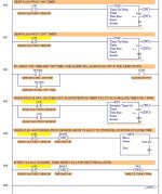
To prevent that from ever happening is very simple. Just use two timers instead of one, as in the attached example. Set the "ON" timer Preset slightly longer than it takes for your flag to pass by. Then if the gear stops with the flag at the sensor, you will still get an alarm in the shortest possible time.

Set your "OFF" timer T4:1.PRE slightly longer than the maximum time for 1 revolution at the slowest speed.

Also, rungs 3, 4, and 5 show how to capture the time for 1 revolution of the gear, and save it to N7:0. I tested this and it works. Then you can use the value of N7:0 to calculate your RPM.

GEAR-TEETH SENSOR & RPM.jpg
 
Last edited:
Great,

Lancie I will give it a shot,

The "machine' is actually a poultry chiller it holds roughly 25,000 gallons of water and 30,000 chickens. The gears turn slowly and are 3 or 4 feet in diameter with a 180 200 chain.

The reason the alarm is important is becouse of the tourque on the auger (14 ft diameter), if one part of the auger were to stop it could literaly blow the end out of the next piece.

Anybody thats ever worked in poultry knows that cheap is best, fourtunately in this economy their not laying off work is always steady.

Thanks for all the help I know I don't post much thanks for jumping on it

Clint
 

Similar Topics

Anybody have any info on the address prefix "B" used on the DL06 units? I am working with 4 Direct Logic DL06 units (D0-06AR) connected to each...
Replies
2
Views
1,734
Anybody have any info on the addressing prefix "B" used on the DL06 units? I am working with 4 Direct Logic DL06 units (D0-06AR) connected to...
Replies
3
Views
1,662
i have a hwk question that i cant get fixed right. attached is the jpeg of what i have done soo far and question is attached as well any help is...
Replies
14
Views
2,287
Hello: I have a micro820 plc with a Spectrum Controls 2080sc-IF4 analong module and a Prosoft 800 SMS module. I have 3 4-20ma pressure sensors...
Replies
1
Views
1,218
Good Morning Everybody, I'm using RSLogix500 and programming a Micrologix 1100. I define all my outputs using B3 data file and reference those...
Replies
5
Views
1,920
Back
Top Bottom