Stumped

I would use the teeth on the gear and count teeth except for the fact that when the gear stops it could easily stop on a tooth keeping the timer from timing? So I made a "flag" (a piece of metal sticking out away from the gear teeth)to limit the likelyhood or the flag stopping over the sensor.
The reason the alarm is important is because of the tourque on the auger (14 ft diameter). If one part of the auger were to stop, it could literaly blow the end out of the next piece.
Because of these two facts, you should consider sensing the gear teeth instead of a flag (target). By the time your flag comes around again, 10 or 20 seconds may have passed and it will be too late to save the next auger. Even the distance of one tooth-travel may be too late, but your chances are a lot better.

By using the two-timer method (ON and OFF times for each gear tooth), you will make sure to get an alarm no matter where an auger stops. That eliminates your main concern for not sensing the gear teeth, and you sure do have a good reason for looking at the teeth instead of at flags.

PS: In my previous program, the Rung 002 comment says "...the alarm will always go off if the gear stops." What I meant was that the alarm will always be triggered -- it will go ON.
 
Last edited:
Great,

Lancie I will give it a shot,

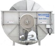
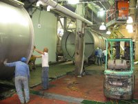
The "machine' is actually a poultry chiller it holds roughly 25,000 gallons of water and 30,000 chickens. The gears turn slowly and are 3 or 4 feet in diameter with a 180 200 chain.

The reason the alarm is important is becouse of the tourque on the auger (14 ft diameter), if one part of the auger were to stop it could literaly blow the end out of the next piece.

REPLY I have no idea what you mean by blowing end out of next piece. I have seen pressure vessels fail and blow but never shafting or mechanical components. The have always bent twisted sheared in my experience.

Anybody thats ever worked in poultry knows that cheap is best, fourtunately in this economy their not laying off work is always steady.

Cheap?? - well you get what you pay for. That is not an accptible concept for the industries I have worked in aircraft submarine repair construction etc. Food product oh yes gobble it together anyway you can. Maybe this kind of thinking is why some peanut outfit went out of business. I did food also - I NEVER ate and NEVER will eat their product.

Back to your problem. The concern is twisting equipment apart. Good concern. I do not see how measuring gear teeth will prevent this. You need to be measuring torque or at minimum have some kind of torque overload device. The oldest and best in my mind is brass shear pins - not good because steel ones are used to replace to satiate the PRODUCTION GOD.
After that torque overload clutch OOOPS gonna cost - in fool plant I worked at we jumpered a torque sensor out (not a human safety concern so I did it - not my equipment and all on company time more job security and PRODUCTION GOD was happy and I did not want to argue common sense and received no flak). The other method is to measure torque if you are using VFD and set in protective parameters. Yes they will get trips - dont throw in so many chickens is the answer
- damn the PRODUCTION GOD.

Dan Bentler
 
The concern is twisting equipment apart. Good concern. I do not see how measuring gear teeth will prevent this.
Dan,
I think Clint intends to use his existing sensor to simulate a zero-speed switch interlock. If an auger sensor shows that an auger has stopped, then the next one upstream must also be stopped immediately or risk "blow[ing] the end out". I suppose that if a 14-feet diameter auger stops, and one upstream of it keeps pumping out chickens, the result could resemble an explosion.

...running the gear at 60 HZ might mean a revolution of 10 seconds and running the same gear at 20 HZ might be a time of 30 seconds per revolution.
Then it seems you need some feedback from the drives to indicate what speed they are running. Then set the PRESET times on your timers to match the drive speed. As the speed is changed, use your PLC program to change the setting of your alarm timers, to minimize the time between auger stop and alarm.

Because you want to keep the cost at a minimum, then use your prox sensor timer to calculate the speed of the last revolution. Then based on that speed, change the settings of the alarm timers on the fly, so they are always slighlty above the time to make 1 revolution at the LAST known current speed. You may need another timer to wait 1 revolution after a speed change is made, before changing the alarm timer Presets. That will help to prevent false alarms.

Yes, now your program is getting complicated, but that is the trade-off when you want to minimize the equipment cost.
 
Last edited:
Dan,
I think Clint intends to use his existing sensor to simulate a zero-speed switch interlock. If an auger sensor shows that an auger has stopped, then the next one downstream must also be stopped immediately or risk "blow[ing] the end out". I suppose that if a 14-feet diameter auger stops, and one coupled to it keeps turning, the result could resemble an explosion.

Lancie

Sure would be nice to have a picture of this setup. I am sure this is all stainless equipment and any purchase requires a water cooled checkbook.

Worked on large maet auger mixer setup 7.5 HP geared down to 20 30 RPM??
I envision some sort of long tank with a 4' dia auger to feed chickens thru. I am sure that this is not one continuous shaft so he does need to worry about if one jams up then he has a busted coupling to work with - been
Been there done that. He says he is driving with 180 chain which is a TORQY chain ie big. This chain may easily transmit 12,000 ft lb torque.

If he uses zero sense switch on rotating auger when switch senses zero RPM it is almost over with and he may have a damaged twisted shaft. I think close monitoring of motor amp or a torque parameter in VFD would be a better method. In that case a zero switch may be appropriate ie
get a jam (they overfed it again)
overcurrent
reverse motor to do immediate stop and unload of drive train
zero switch stops unit
clear jam.

Dan Bentler
Dan
 
That picture is worth 10,000 words. The drive is about the same as that I worked on on the mixer. We had coupling between the final drive sprocket and the shaft (poorly done retrofit from hydraulic to elcetric drive). When it came apart the second time it twisted and bent the 5/8 key to a 45 angle.

For sure I would have torque limiting control on this either by motor current or if you can in VFD. I would for sure have some way to bring this motor to a near instaneneous stop either via VFD or zero rev switch combined with plugging. Might even tie that in with the E stop circuit - may come in handy when someone gets an arm in that - that machine is NOT going to even think about slowing much less stop for some flimsy human arm.

Dan Bentler
 
I would recommend the following.
Program a latch bit (B3/xx) that comes on when the sensor turns off. Use B3/xx to run a RTO timer. When the latch bit is ON and the sensor turns ON, unlatch B3/xx and move the value of the RTO current valve into a word. Then you can compute the RPM by calculating the number of sensor flashes per revolution and the time delay per sensor flash. Once the computation is completed, reset the RTO. This method is technically "not real time" but it will get you real close.
 

Similar Topics

Anybody have any info on the address prefix "B" used on the DL06 units? I am working with 4 Direct Logic DL06 units (D0-06AR) connected to each...
Replies
2
Views
1,717
Anybody have any info on the addressing prefix "B" used on the DL06 units? I am working with 4 Direct Logic DL06 units (D0-06AR) connected to...
Replies
3
Views
1,658
i have a hwk question that i cant get fixed right. attached is the jpeg of what i have done soo far and question is attached as well any help is...
Replies
14
Views
2,282
Hello: I have a micro820 plc with a Spectrum Controls 2080sc-IF4 analong module and a Prosoft 800 SMS module. I have 3 4-20ma pressure sensors...
Replies
1
Views
1,217
Good Morning Everybody, I'm using RSLogix500 and programming a Micrologix 1100. I define all my outputs using B3 data file and reference those...
Replies
5
Views
1,915
Back
Top Bottom