Analog I/O in AllenBradley PLC5

Frelecing

Member
Join Date
Oct 2010
Location
Uruguay
Posts
73
Hi everyone:

It's my first time working with analog I/O on a PLC, so I am a little lost.
I have the ladder code that's in a PLC in my company and we have to make some changes.

As the change will be to add another mill and electromagnetic vibrator, just as one we already have, the idea is to copy and paste the section of the program that controls the original. But I cannot find the portion of the code that refers to the original mill/vib.

I have identified the connection of the 2 analog signals I need (this are: an amperimeter from the mill, and the signal that controls the magnitude of the vibration)

In the plc I have 3 analog cards, one 16-point input (1771 IFE) located in Rack0, Slot 2* of the chassis, and 2 4-point output (1771 OFE1), located in Rack0, Slots4.

The Amperimeter is connected to the first terminal of the input card (this is input 1 or 0?), and the mill is connected to the 2 terminal of the second output card.
My guess is that the should be addresed in the code as I:002/0 and O:006/1. I can't find any reference to those I/O , but as I am just guessing how analog I/O work I maybe completely wrong. So if anyone can explain me, as a very basic tutorial ("analog PLC I/O for dummies") I will be more than grateful.


Thanks!

*If I have 4 slots in one rack, they are named, 0 2 4 and 6, aren't they?
 
First tell us the what PLC5/?? you have. A PLC5/?? does not use input/output addresses for analog modules like the SLC500 does. A PLC5/?? will have block transfer instructions to read/write to the analog modules, they use integer addresses like e.g. N29:0.
Post your .RSP file (zip it first) and someone will help you find the addresses.

With a 1771-IFE analog input module channel numbering starts at "Channel 1"
With a 1771-OFE analog ouput module channel numbering starts at "Channel 1"

This is not true for all AB analog modules some do start at "Channel 0", check the manual to be sure.
 
Last edited:
what is your analog input signal.is it 4-20ma or 0 to 5v.open the analog module and configure the jumper setting according to analog signal you use.then you have to write BTW AND BTR instruction in your programme in order to work with analog module.to know how to programme it is needed to foloow the instruction manual of the module.
 
From the program you posted ( no documentation) here is my best guess.
It would really help if you had a copy of the program with some documentation.

The first channel of your analog input card Raw Data input would be address N7:72 then some scaling to N7:161.

The second channel of the first analog output card would be N7:145 and N7:150 of the second analog output card.

Hopefully someone else will jump in the confirm or?? my findings.
 
It would really help if you had a copy of the program with some documentation.
I know! It would be really helpful for me too! But we have none, this code was made by someone else like 3 years ago, and when he left the company, he took the project with him (a really nice guy)... Now I come to the scene :oops:, and what I could do was too upload the code that was in the PLC, but there are no coments, nor any kind of documentation whatsoever.

The first channel of your analog input card Raw Data input would be address N7:72 then some scaling to N7:161.

The second channel of the first analog output card would be N7:145 and N7:150 of the second analog output card.

How did you figure this out???

Thanks, once again!
 
Since the IFE will have analog inputs, there will be a BTR instruction for it. Searching the program, there is only one BTR. There is also a BTW for that card for the purpose of configuring the card scaling.

For the analog outputs, there will be a BTW for each card, and often a BTR to read back the scaling data.

It would be very beneficial to document what you have, so that the documentation in the RSLogix5 program can be updated to match your system. Once RSLogix5 "knows" where these card are located and how they're configured, you can take advantage of the built in configuration tools which makes it much easier to make chages opposed to poking numbers in a data table.

Some of the details you need are going to require that you pull cards and check jumpers. Are there opportunities for you to shut the PLC down and check the jumpers on the analog cards, and the backplane jumpers?

The main thing to start documenting is going to be the slot addressing mode (1/2, 1, or 2 slot addressing).
EDIT: According to the processor status, you're using 1/2 slot addressing.

Can you tell us the physical size (how many slots) of the rack(s)?

And, make a list of the cards in the rack. We can then populate the I/O config in RSLogix5 to match your system, and begin the process of adding documentation.

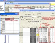
Example based on guesses:

hidra_000.jpg
 
Last edited:
go to the i/o chaneel overview to see the integer files corresponding to the channel. if you know the hardwire that which channel it use , you will get the corresponding integer files for that channel.
earlier i was using this with dos based 6200 software series.
it must be in rslogix5.
 
How did you figure this out???

See OkiePC's first two sentences. The BTR/BTW's are located in Lad 15.
With that knowledge and the manuals for your modules you can figure it out.
 

Similar Topics

Hello all I am using a controllogix 5000 controller with a DHRIO scanner. I am then connected to a 1747 ASB (SLC family) rio adapter. I am...
Replies
4
Views
4,533
Hi all. Customer wants analog faceplates really bad, even if we explained that it doesn't make much sense in his process. What he wants to see...
Replies
5
Views
91
I'm having trouble calming down 2 Tempo Sonics. I'm using Studio 5000 CompactLogix my Raw value is jumping around from 8575.0 to 8755.0 at a...
Replies
30
Views
1,094
I cannot add SLC500 analog input tag (I: 8.3) to EZSeries Touch Panel Editor (V 5.3). I used all the listed tag datatype but it all says "Invalid...
Replies
10
Views
248
Hi, I have questions. I have Analog Input that need to put into Ignition Designer. But I don't know how to put?
Replies
1
Views
109
Back
Top Bottom