1794-OE12-Help me

Join Date
Nov 2009
Location
India
Posts
116
Hi

I installed 1794-OE12 flex IO, the module power LED starts blinking, then I turned ON the module enable bit and resetted the Wire Off reset bit, now the module is OK and i can able to force values and measured the result also its fine.

I am facing problem, when i got channel open wire the output will be safe state value what we configured, but when the open wire got rectified physically still it shows the same value, then after i reset the wire off reset bit from software and got ok.

My question is eventhough the fault rectified physically but the module requires the reset. How to program for this bit and is there any option to make automatically reset. Also this reset is for whole module whatever actually got wire break also:doh: reseting to zero and turn on again to 1. This is a big problem as i need to show alarm in SCADA.

Kindly anyone help me plsssssssssssssssss...............
 
It might help if you tell the forum what processor you have, how is the module connected to to processor ( Ethernet,Controlnet, Devicenet,Remote I/O)
 
Processor: L35E

Communication: Ethernet

Whatever the processor and communication the module properties remains the same.

It always amazes me when a poster says that you really don't need to know what I am doing. Just give me the answer to my question.

It is pretty much the same as saying. "I have a car, how do I fix the engine?"

Details are important. The Flex I/O can be used with a number of PLCs, and a number of Communication Protocols. They are all implemented a little differently on each PLC, and communications Protocol. Better information will allow a better answer. It is that simple.

Stu.....
 
I had one processor and one Flex IO.

My communication protocol is ethernet.

Pls let me know if any more details wanted.

Ok, complete part numbers are always preferred. I am going to assume you mean the Compact Logix 1769-L35E. I did a couple of quick searches, and found the following.

The tables did not copy over from the following Word document, so I have attached the original Tech Note as well. In your PLC Code, monitor the Channel Broken Wire Bit, and Reset with the WireOffReset when the Input Goes False agin if you want to do it automatically. Other options are to set an Alarm so you are aware of the problem, then reset it manually when you have investigated and rectified the problem.

Stu.....


Additional Explanation:

- If the Output Module (1794-OE12, 1794-IE8XOE4) detects a continuous OpenWire (:I.Ch[x]OpenWire) condition for more than 20 seconds, the effected Output Channel will be disabled
- To re-enable the Channel you will need to Reset the condition using the Wire Off Reset (O.WireOffReset) bit

OK light blinking green
- If the EN bit for the outputs is not set or if your are writing to the lower bits of the first write word (11 through 0) the OK Led will blink green

User Manual:
http://literature.rockwellautomation.com/idc/groups/literature/documents/in/1794-in106_-en-p.pdf


Configuration and Troubleshooting Tips for Flex High Density Analog Modules 1794-IE12, 1794-OE12 & 1794-IE8XOE4


Wire-Off

For the 1794-OE12 and 1794-IE8XOE4, a Wire-Off Status bit (for a current output channel) will be set in the Status Word, and can be read by the customer.

The Wire-Off Reset bit enables all current outputs channels again, and is shown in the Installation Instruction on Page 4
(Write Word 0, Bit 12, WR = Wire-off Reset): http://literature.rockwellautomation.com/idc/groups/literature/documents/in/1794-in106_-en-p.pdf

The 1794-OE12 data table is shown for reference:


Behavior of the 1794-OE12 and 1794-IE8XOE4 Current Outputs (0-20mA or 4-20mA) during a Wire-Off Condition:

When an Output channel circuit on a 1794-OE12 or 1794-IE8XOE4 detects an open wire, the Wire-Off Status bit for that channel will be set.

The module will attempt multiple times to drive the current output into an open or high resistance load:

· If the wire-off condition is present during the retry, the Retry Count will increment by one, to a maximum of 8.
· If the wire-off condition is not present during the retry, the Retry Count will decrement by one, to a minimum of 0.
· After approximately 20 seconds of a continuous wire-off condition (8 retries x 2.5 seconds), the current output drive circuit is disabled for that channel (0mA), and the Wire-Off bit for that channel will be set to "1".

During these retries, the Wire-Off Status bit may toggle On/Off as the output channel drive circuitry tries to turn the current output on.

Normally, the Wire-Off Status bit would be latched by the customer program on the first occurrence, and set an operator alarm, so this should not be a problem; the wire-off condition has been detected, and the module will attempt to reconnect to the load.

1. The operator would then inspect and verify the I/O device or wiring to find the cause of the Wire-Off alarm.

2. They would send a Wire-Off Reset command by toggling (0 > 1 > 0) the Wire Reset bit (Bit 12 of the Reserved Write Word). This would instruct the module to restart the current output drive / retry sequence again.

3. They would manually reset the latched Wire-Off status bit in their control program

4. Normal current output operation would resume.

LEDS

OK LED

All Modules


Off: No Backplane Power
Solid Green: Normal Operation
Blinking Red: Minor Fault
Solid Red: Major Fault

OK LED

Blinking OK LED on the 1794-IE12

· Enable Module bit is set to 0 (Reserved Word, Write 0, Bit 15).
· Configuration Word (Configuration Word, Write 1, Bits 0-11) is set to 0 (all channels unconfigured).
· Controller is in Program / Idle mode, and not Run mode.
Blinking OK LED on the 1794-OE12,

· Enable Output bit is set to 0 (Reserved Word, Write 0, Bit 15).
· Configuration Word (Configuration Word, Write 13, Bits 0-11) is set to 0 (all channels unconfigured).
· Controller is in Program / Idle mode, and not Run mode
· Power Supply Common not connected or connected improperly

Blinking OK LED on the 1794-IE8XOE4

· Enable Output bit is set to 0 (Reserved Word, Write 0, Bit 15).
· Configuration Word (Configuration Word, Write 1, Bits 0-11) is set to 0 (all channels unconfigured).
· Controller is in Program / Idle mode, and not Run mode
· Power Supply Common not connected or connected improperly

The "First Write Word" Clarification

Ref. 1794 High Density Analog Installation Instruction 1794-IN106B-EN-P, dated December 2005

Currently, Word 0 is called "Reserved", since for the IE12, 15 of 16 bits were reserved and for the OE12 and IE8XOE4, 12 of 16 bits were reserved.

1794-IE12:


1794-OE12, IE8XOE4:


There have been some questions if it is Reserved or not since "Reserved" usually means all 16 bits.
The next update to the data table will change the description as follows:

Present: Write Words 0 - Reserved

Proposed: Write Words 0 - Output

Notice there is no suffix number after it, so it is not confused with an "Output Channel".
It is not Config either, since the Config Data follows the Output Data.

 
Thanks for your Detailed Explanation.

So, still i need to reset the wire off reset bit manually. there is no control logic to re-enable the channel automatically.
 
Thanks for your Detailed Explanation.

So, still i need to reset the wire off reset bit manually. there is no control logic to re-enable the channel automatically.

No, you will have to write the PLC Code to perform the reset if that is what you want to happen. There shouldn't be an open wire fault unless something happens to cause a disconnect. Which in most applications is not normal. I did not research it in this case, but I would imagine you can prevent nuisance faults by disabling unused channels. Just a guess though. Only you know your application and hardware setup.

Stu.....
 
Hello!

I have some problems with 1794-OE12. I set a module. But indicator "OK" is blinking. How to config right the module? I do how it's in instruction, but nothing...
 
It always amazes me when a poster says that you really don't need to know what I am doing. Just give me the answer to my question.

It is pretty much the same as saying. "I have a car, how do I fix the engine?"

Details are important. The Flex I/O can be used with a number of PLCs, and a number of Communication Protocols. They are all implemented a little differently on each PLC, and communications Protocol. Better information will allow a better answer. It is that simple.

Stu.....
It always amazes me the level of OCD in the Engineering community, if you don't have constructive comments, say nothing, of course, I have just added to the fire by tossing in my dos centavos.

So, for example the 1794-OE12/A Ana out card has a wonderful feature that disables the device, until a bit reset, if the the analog device receiving the signal drops out. For example, we have a 3 phase drive that has a disconnect used for a lockout device. Now, when powered down, our lovely "broken wire alarm is active" and no analog signal is produced.

IMHO, this is one of those devices Rockwell should scrap, but hey, we are changing platforms anyway.


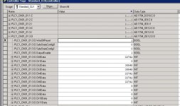
ANALOG_RESET.jpg
 
Thanks guys. Sometimes I can find information on Rockwell Automation tech documents... But most of the time I feel as Data says "pursuing an untamed ornithoid without cause." Why would this information not be included in the User Manual for the Card? You helped me regain my sanity after trying to get a simple 4-20mA signal out of the 1794-IE8XOE4 card.
 

Similar Topics

Hello! I have a problem with ControlNet... I have a ControlNet wich consists from 7 flexbuses. In one FlexBus I need change AO module 1794-OE4...
Replies
1
Views
1,675
Hi Friends, I'm facing problem in 1794-oe12 flex i/os. Im not getting 4-20ma output. i hope its a self powered. only module supply...
Replies
12
Views
14,369
Hi, Can anyone help me? I have limited space on a flex I/0 rack and wanted to use a 1794-OE12 but am not sure this is compatible with PLC 5 /...
Replies
4
Views
1,928
what magic do i need to do to get the 1794-oe12 analog output card to give me my 4-20 ma it was configured to do. i am using a rslogix5000...
Replies
1
Views
2,309
I am having issues locating the status codes and figuring out why I don't have any output from my analog output card. Here's the configuration as...
Replies
7
Views
4,873
Back
Top Bottom