Automating two seperate linear actuators

richard0956

Member
Join Date
Jun 2014
Location
Yorkshire
Posts
15
Hi. I've got to a stage where I am able to draw a ladder circuit involving relays which will send a horizontal gantry on rails to the right end stop, then after a second automatically reverse the gantry back to the horizontal home position.

Of course I employed limit switches on both ends of the rails.

But, I'm getting stuck progressing to automating two gantries.

Say I have two gantries - vertical (V) and horizontal (H). I want to push a start button: The H gantry moves to right end stop and stops, then the V gantry moves down to bottom end stop, then after a second, goes back to top end stop, at which point the H gantry moves back to home position.

The problem I have is this: By what means does the machine know when to start moving the H gantry back to home position?

In other words, how does the machine differentiate between a home position (V gantry at top end stop) of the V gantry before it starts out on it's journey (down and back again) and the home position after the V gantry has completed it's journey?

Thanks.
 
Last edited:
You have discovered the differenxe between combinitorial logic (where the current state of inputs and outputs determine the next action) and sequential logic (where the history of the system is also a factor).

You will have to experiment with control relays latching in when certain conditions occur and their contacts are used in addition to the inputs to trigger the next action.

1. Start button is pressed and H gantry is on the left stop. latch in first sequence control relay.

2. First sequence (and not second) is active - move the H gantry toward the right. It hits the right stop - latch in the second sequence relay.

3. Second sequence (and not third) is active - move V gantry down. It hits the bottom stop - wait one second then latch in the third sequence relay.

4. Third sequence (and not fourth) is active - move V gantry up. It hits the top stop - latch in the fourth sequence relay.

5. Fourth sequence (and not fifth) is active - move H gantry toward the left. It hits the left stop - latch in the fifthe sequence relay.

To repeat you'll have to either reset the system or let the fact that the fifth sequence relay is on reset the rest (it would probably only have to reset the first sequence relay if your design requires the previous relay to be on for the next to stay latched in.)

Obviously the control relays provide the "history".
 
Last edited:
That is a great explanation, Bernie.

Richard, for better help, list everything you know, including your PLC brand and model, your software name and version, and your I/O list (detailed list of Inputs and Outputs, with name of each and PLC address).

Print and ZIP what you have and attach it to your next post.
 
Last edited:
In that circuit CR2 and CR3 will also energize after CR1 in a VERY SHORT amount of time (the amount of time for the relay contacts to move from one side of a relay to the other.) All three will stay on until the stop button is pressed.

[Edit - On a second look I think the diagram is implying that there are 3 seperate Start buttons - even though there was no differentation in the name of each. In that case, yes, it has a bit more relevance. Each start button represents the conditions necessary to send the action to the next step.]

I'm spoiled by PLCs. This would be a couple minute's programming with a very small one.
 
Last edited:
Hi. I think what I'm learning here is that in order to make use of a limit switch on the top of the V gantry to allow for the next sequence, it is necessary to create an AND gate - consisting of two switches in series - one the top limit switch, the other the contacts of a latch relay.

So, it needs to be a condition for the V gantry to move down (after the H gantry has got to the right) that a) the top limit switch on the V gantry is closed (indicating V gantry is at top or it's home position). And b) that the previous sequence (H gantry set off moving to right) has taken place. Of course that information is indicated by a latch relay's contacts being in a closed position.

Similarly, the condition required for the H gantry to return home after the V gantry gets back to it's home position, is the top limit switch is closed, and that another set of latch relay contacts are closed, the latch specifically associated with the previous sequence.

I think I understand in the case where there are four motors: That is - one moves H gantry right, another moves it left; one moves V gantry down another moves it up.

Bit more complicated when only two motors are used.
 
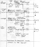
Here is my circuit for automating V and H gantries using 4 motors.

Motor 1 moves H gantry left to right
Motor 2 moves V gantry top to bottom
Motor 3 moves V gantry bottom to top
Motor 4 moves H gantry right to left

FIRST LADDER

Press start. Left H limit is closed when H gantry is at left. Right H limit is open when H gantry on right. CR1 energizes and CR1-1 seals start button. CR1-2 seals left H limit. Motor 1 runs, until reaches right. Latch relay LR1 energizes closing LR1 contacts.

SECOND LADDER

Right H limit is closed when gantry is at right. Top V limit is closed when V gantry is at top. Contacts LR1 are closed. Bottom V limit is closed when V gantry at bottom. So, CR2 energizes the moment H gantry gets to right end. CR2-1 seals top V limit. Latch relay LR2 energizes as well closing contacts LR2. Motor 2 takes V gantry towards bottom and stops when at bottom.

THIRD LADDER

Right H limit is closed when gantry is at right. Bottom V limit is closed when V gantry is at bottom. Contacts LR2 are closed. Top V limit is closed when V gantry at top. CR3-1 seals So, CR3 energizes the moment V gantry gets to bottom. Latch relay LR3 energizes closing contacts LR3. Motor 3 takes V gantry to top and stops when at top.

FOURTH LADDER

Right H limit is closed when gantry is at right. Contacts LR3 are closed. Left H limit is open when H gantry is on left. So, CR4 energizes the moment V gantry gets to top. CR4-1 seals right H limit. Motor 4 takes H gantry to left and it stops when it reaches the left (home) position.

There is no means here to reset the latches.

4 motor automation V and H gantry.jpg
 
Last edited:
Yes, interlock the 4 motors, so that both horizontal-travel motors can NEVER be allowed to be ON at the same time, and the same for vertical travel motors.

Also, you have drawin your latching relay contacts as if the system was running and LR relays are energized and the Normally Open LR contacts are closed. The conventonal wisdom is that circuits are drawn as if everything is in the de-energized state. Normally Open contacts should be shown as open, and Normally Closed contacts should be shown as closed.

You should not need the Latching relays. As you pointed out, they are a problem when you try to STOP the system. In order to STOP, you have to somehow unlatch those relays. It would be better to use normal relays and seal-them in with a holding contact, so that they all drop out when someone hits STOP.
 
Last edited:
Okay, I should draw all contacts as if relays are in un-energized state and gantry mid-travel.

I thought I needed latching relays so that the system knew the difference between a) a gantry that is in a state ready to be driven from it's home position and b) a gantry that is in home position after having traveled and done it's thing.

For instance, just before the H gantry goes back you ought to be sure V gantry is in it's home position which is at the top. Well, a simple limit switch can tell you that V gantry is at top, but not whether it's ready to be driven, or its just finished its traveling. That is why LR3 and it's contacts are included. Am I missing something? :)

Not sure whether I need every latching relay I've drawn.
 
Last edited:
The thing is, the way I've drawn my circuit if I did not have at least LR3, both CR2 and CR4 would be on at the same time, when the V gantry is at top.
 
Well, you do need relays that indicate what Step the process is in, as mentioned by Bernie back in Post #3. He did call them "latching" but really I think in this case they should be regular relays that get self-sealed (does the same job as latching relays) but can easily be un-sealed simply by deenergizing the seal-in circuit.

If you do choose to use the latching-type relays, then you need logic to unlatch each (maybe unlatch all at once) when the gantry returns to Home position, and before the circuit shuts down. For instance, you might use the "simple limit switch" in combination with LR3 ON to tell you that the gantry is back at Home AND all the steps have been completed. Now use LOGIC something like this so that it is only executed AFTER LR3 has been latched ON:
 
| TOP LIMIT SWITCH LATCHING RELAY 3 UNLATCH LR1 |
|---------| |----------------| |----------+------(U)------|
| | |
| | UNLATCH LR2 |
| +-------(U)-----|
| | |
| | UNLATCH LR3 |
| +-------(U)-----|

 
Last edited:
I have an issue with ladder #2.

As I've drawn it, CR2 activates motor 2 (M2) which takes the V gantry to the bottom. CR2 is activated when the H gantry gets to the right end stop. M2 will stop when the V gantry hits the bottom limit switch breaking the circuit.

I've also put the V gantry top limit in circuit sealed by CR2-1. The top limit is closed when the V gantry is at top, so when right H limit switch closes, CR2 can be energized. But, once V gantry moves off top limit top V limit must be sealed, otherwise the gantry would stop. When the circuit is de-energized as V gantry hits bottom limit, the seal CR2-1 is broken. Now, when the V gantry begins it's upward movement (CR3/M3 does that) the bottom limit closes again, but the circuit cannot be energized once again because there is no seal around the top limit switch, which is open until the V gantry hits top.

But, there is a problem, when the V gantry hits top we get the initial conditions. So, immediately M2 will want to send the V gantry down again.

I think the way you solve this is putting in a latch relay operated by a NO limit switch at the V gantry bottom. When the V gantry hits the bottom it energizes a latch relay whose contacts are in series with the CR2 circuit. This latches open. So, this means once M2 takes the gantry to the bottom, even though M3 takes the V gantry to the top, CR2 and thus M2 can never be again activated, until that latch is reset.

This means I would not need to connect in series a top limit with seal CR2-1. These would be superfluous.
 
Last edited:
We used to program PLC's in what was called half-cycle logic to save space. It used a minimum of internal coils and all the outputs appeared in the body of the sequence logic. It was also termed conditional logic - if the conditions were met, then the output was turned on/off. In order to solve the issue that you are experiencing, we used an internal coil named "half-cycle" so that approximately half way through the sequence we turned it on and that allowed for the retracting of the motions through the remainder of the cycle.
 

Similar Topics

There is a very old manually operating hydraulic forming press in our production. At the moment it's out of operation due to some issues with the...
Replies
17
Views
6,115
As a newcomer to RSLogix, I keep reading about (and am quite interested in) how companies automate tagname creation and have libraries of...
Replies
15
Views
5,637
Since rslogix 5000 does not have vba, is there a better way to automate programming tasks than using vba to generate an L5X file?
Replies
1
Views
1,820
Question for you guys who work for yourselves or for companies as programmers: What is the process by which your customers convey to you the...
Replies
10
Views
3,806
I'm looking for a quick advice. To all you guys that have automated a machine, what are the steps that you follow to developed your project? Do...
Replies
12
Views
3,107
Back
Top Bottom